
Efficient Scheduling of Background Scrub Commands

a scrub command and scrub command technology, applied in the field of memory controllers in computer systems, can solve the problems of hard or soft errors, corruption presents itself as a “soft error”, and the hard error is a permanent error, so as to reduce or eliminate the impact of scrub on the throughput of the computer system

Inactive Publication Date: 2009-03-12
IBM CORP
View PDF5 Cites 15 Cited by
  • Summary
  • Abstract
  • Description
  • Claims
  • Application Information

AI Technical Summary

Benefits of technology

[0008]To reduce the likelihood of uncorrectable multi-bit errors, therefore, memory is scrubbed over a specified scrub period. For example, an entire memory of a computer system may be scrubbed over a twenty four hour scrub period. Specified memory reliability rates rely on completion of scrubbing all memory in the specified period.
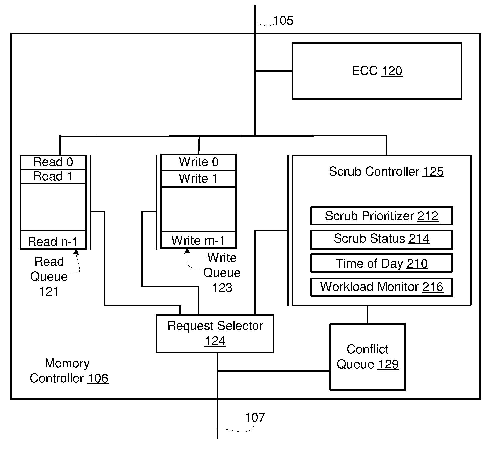
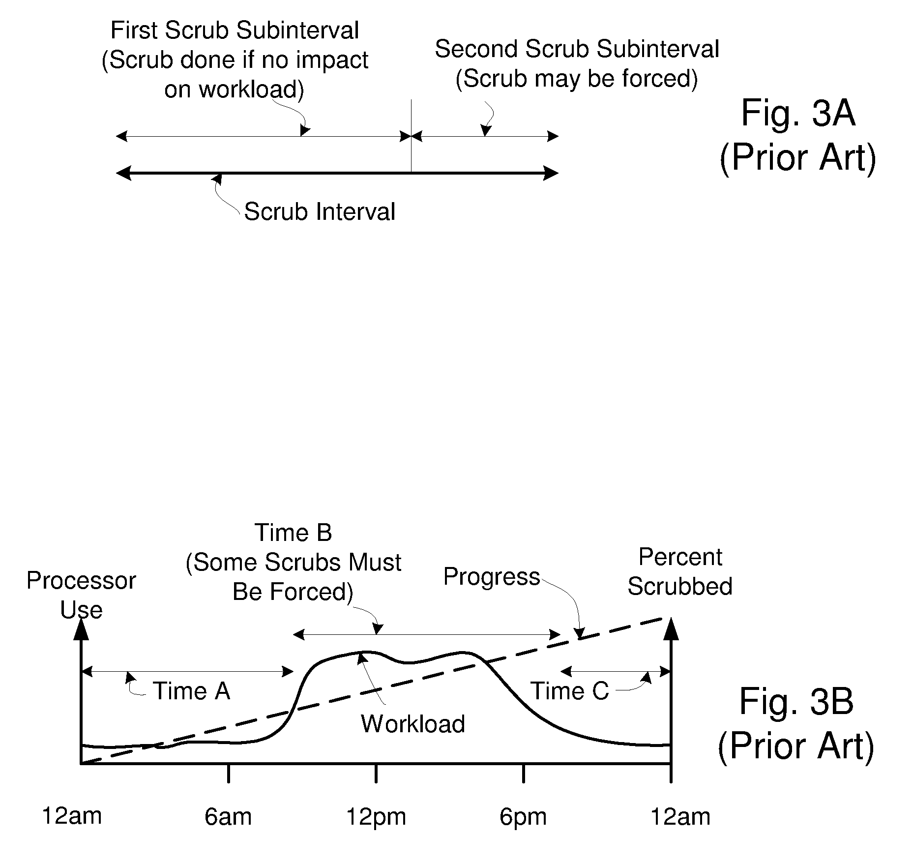
[0012]Conventional memory controllers present a single scrub request at a time to a request selector, stepping scrub requests in order through banks and ranks of memory chips in a memory to which a processor makes read and write requests. The request selector is coupled to a read queue, a write queue, a conflict queue, and a scrub controller. If the single scrub request presented would delay a read request (or, possibly a write request in some situations), or can not be performed because of a conflict identified in the conflict queue, the scrub request must wait, often until the second scrub subinterval occurs and a scrub demand must be forced, meaning that the scrub request is handled even at the cost of adding latency to a read request or a write request.
[0013]Embodiments of the present invention provide methods and apparatus for reducing or eliminating impact of scrubbing on throughput of a computer system.

Problems solved by technology

Often this corruption presents itself as a “soft error”.
The SBE may be a permanent error (a physical error in the memory or interconnection to the memory) or the SBE may be a “soft error”.
Further suppose that the first soft error is left uncorrected, and, after a period of time, a second error (hard or soft error) occurs in the particular cache line.
A “hard” error is a permanent error, for example, a broken signal connector, or a failing driver or receiver.
The ECC circuitry is not capable of correcting a cache line having two errors, and reports that an error has been detected but can not be corrected, resulting in likely termination of a task requesting the particular cache line, and possibly requiring a re-boot of the computer system.
Demand scrubs reduce throughput of the computer system because they increase latency of read and write requests, causing a processor to wait for data.
During Time B, memory demand workload is relatively heavy, and it often occurs that scrub requests can not be serviced during a first scrub subinterval of a scrub interval.
An access to a particular bank in a particular memory rank takes a certain amount of time to complete, and subsequent accesses to that particular bank in the particular memory rank can not be made for the certain amount of time.

Method used


Image

  • Efficient Scheduling of Background Scrub Commands
  • Efficient Scheduling of Background Scrub Commands
  • Efficient Scheduling of Background Scrub Commands

Examples


embodiment 700

[0062]FIG. 8 shows a high level flow chart of a method embodiment 700 of the invention. Method 700 begins at step 702. In step 704, a scrub slack value is determined. If the scrub slack value is “positive”, scrubbing is “ahead of schedule”, that is, is in the region denoted ahead 131 in FIG. 4A. If the scrub slack value is “negative”, scrubbing is “behind schedule”, that is, is in the region denoted as behind 132 in FIG. 4A. In step 706, memory workload is determined, indicating whether the memory is currently very busy handling requests for reads (and, perhaps, writes) that have been issued by a processor. In step 708, a scrub rate is adjusted, using the scrub slack value and the memory workload. If memory workload is relatively low, scrub rate is increased, by prioritizing scrub requests over some number of read (and, perhaps, write) requests, if necessary. If memory workload is relatively high, scrub rate is decreased, allowing few, if any, scrub requests to add latency to a read...

first embodiment

[0070]FIG. 10A shows step 706 (FIG. 8) in more detail, denoted 706A in FIG. 10A, beginning at step 720. In step 722, a measurement of fullness of a read queue is made. For example, if the read queue has 32 read request positions, and is currently holding four read requests, the read queue is one eighth full. Step 724 similarly determines fullness of a write queue. Step 726 similarly determines fullness of a conflict queue in implementations having a conflict queue. Step 728 determines memory workload using the values for read queue, write queue, and conflict queue fullness. If one or more of those queues are full or nearly full, memory workload is very heavy; if all of those queues are empty or nearly empty, memory workload is relatively light. Step 729 completes the expanded method of step 706.

second embodiment

[0071]FIG. 10B provides step 706 (FIG. 8), denoted 706B in FIG. 10B. Step 730 begins method 706B. In step 732, time of day is determined by reading a time of day clock. In step 734, memory workload is determined by using the time of day determined in step 732 and a predetermined estimate of memory workload that is stored in the computer system, for example, in the way of a table of workload demand versus time, or an equation. Step 739 ends method 706B.

[0072]FIG. 11 is an expansion of step 708 (FIG. 8) which adjusts a scrub rate. Method 708 begins at step 750.

[0073]In step 752, a duration of a scrub interval is adjusted, using memory workload and scrub slack value. For example, if the scrub slack value indicates that scrubbing is currently “behind”, the scrub interval is made shorter, so that more scrub requests are considered in a given amount of time, and more instances of the second scrub subintervals, where scrubs are forced at the expense of read request (or, perhaps, write requ...


PUM


Abstract

A method and apparatus to efficiently scrub a memory, during a scrub period, of a computer system that has a memory comprising a number of memory elements. Examples of memory elements are memory ranks and banks. A memory rank may further comprise one or more banks. The computer system has a memory controller that receives read requests and write requests from a processor. The memory controller includes a scrub controller configured to output more than one scrub request during a particular request selector cycle. The memory controller includes a request selector that services a read request, a write request, or one of the scrub requests during a request selector cycle.

Description

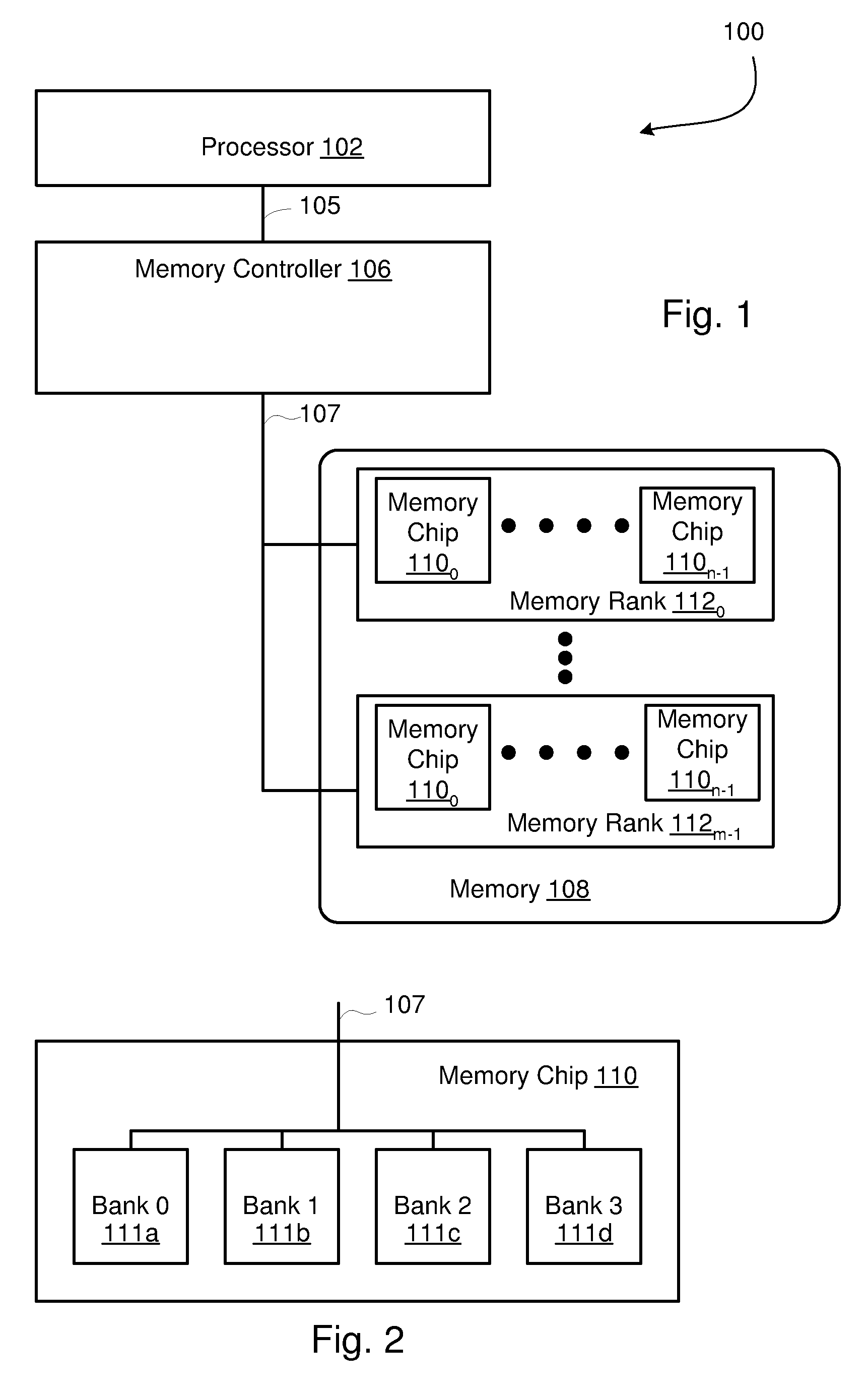
CROSS-REFERENCE TO RELATED APPLICATIONS[0001]This application is related to:[0002]U.S. application Ser. No. ______, filed on ______, 2007, Attorney Docket No. ROC920070118US1, entitled Scheduling of Background Scrub Commands to Reduce High Workload Memory Request Latency.FIELD OF THE INVENTION [0003]This invention relates generally to memory controllers in computer systems. More particularly this invention relates to efficiently scheduling scrub commands.BACKGROUND AND SUMMARY OF EMBODIMENTS OF THE INVENTION [0004]Modern computer systems comprise a memory and a memory controller. In memory, such as DRAMs (Dynamic Random Access Memory) or SRAMs (Static Random Access Memory) for examples, data stored in the memory may become corrupted, for example by one or more forms of radiation. Often this corruption presents itself as a “soft error”. For example, a single bit in a block of data read (such as a cache line that is read) may be read as a “0” whereas the single bit had been written as...

Claims


Application Information

Patent Timeline
IPC IPC(8): G06F11/00
CPCG06F11/106
Inventor ALLISON, BRIAN DAVIDKIRSCHT, JOSEPH ALLENMCGLONE, ELIZABETH A.
Owner IBM CORP
Learn More