Diesel engine system and method of controlling diesel engine

a diesel engine and diesel engine technology, applied in the direction of engine starters, electric control, instruments, etc., can solve the problems of deterioration of fuel economy, more frequent replacement of glow plugs, and deterioration of starting performance, so as to improve the restartability of diesel engines and high fuel economy

Inactive Publication Date: 2009-03-12
MAZDA MOTOR CORP
View PDF0 Cites 31 Cited by
  • Summary
  • Abstract
  • Description
  • Claims
  • Application Information

AI Technical Summary

Benefits of technology

[0007]The present invention is intended to overcome the aforementioned problem of the prior art. Accordingly, it is an object of the invention to provide a diesel engine system and a method of controlling a diesel engine capable of achieving enhanced restartability of the diesel engine after an automatic engine stop while providing as high fuel economy as possible.
[0009]This method of controlling a diesel engine causes the piston of a particular cylinder to stop at a position appropriate for subsequent engine restart upon fulfillment of the engine stop condition, making it possible to provide enhanced engine restartability. Generally, it is necessary in the diesel engine to inject the fuel into a compression stroke cylinder at engine stop and induce self-ignition of an air-fuel mixture formed in that cylinder. It is therefore preferable that the piston in the compression stroke cylinder at engine stop would stop at a point as close as possible to the bottom dead center because it increases the temperature in the cylinder when it reaches at the top dead center at an engine restart.
[0010]The method of the first aspect, by positioning the piston of the compression stroke cylinder at a first stop position that is closer to the bottom dead center than to the top dead center, may increase the effective compression ratio of and the temperature in the compression stroke cylinder at an engine restart. As a result, it may improve the engine restartability.
[0012]In this method of controlling a diesel engine, if the piston in the compression stroke cylinder at engine stop is located generally at an appropriate stop position, the fuel is injected into the compression stroke cylinder at engine stop and a starter motor is run to compress an air-fuel mixture formed in the compression stroke cylinder, thereby inducing self-ignition therein and restarting the diesel engine. If the piston in the compression stroke cylinder at engine stop is displaced from the appropriate stop position toward the top dead center, the fuel is injected into the intake stroke cylinder, and not the compression stroke cylinder at engine stop. Although operating time of the starter motor slightly increases in this case, it is possible to securely induce self-ignition of an air-fuel mixture at a sufficiently high effective compression ratio, thereby providing enhanced engine restartability.
[0014]This diesel engine system is configured such that the pistons are stopped at positions appropriate for subsequent engine restart upon fulfillment of the engine stop condition, thereby providing enhanced engine restartability as described above with respect to the first aspect of the invention.

Problems solved by technology

A problem often encountered with a diesel engine having an automatic stop / restart feature is deterioration of starting performance which is caused by a reduction in engine temperature occurring after the automatic engine stop.
Although intended to improve ignitability (restartability) of the diesel engine, the aforementioned approach of the Publication will cause deterioration of fuel economy and more frequent replacement of the glow plugs.

Method used


Image

  • Diesel engine system and method of controlling diesel engine
  • Diesel engine system and method of controlling diesel engine
  • Diesel engine system and method of controlling diesel engine

Examples


Embodiment Construction

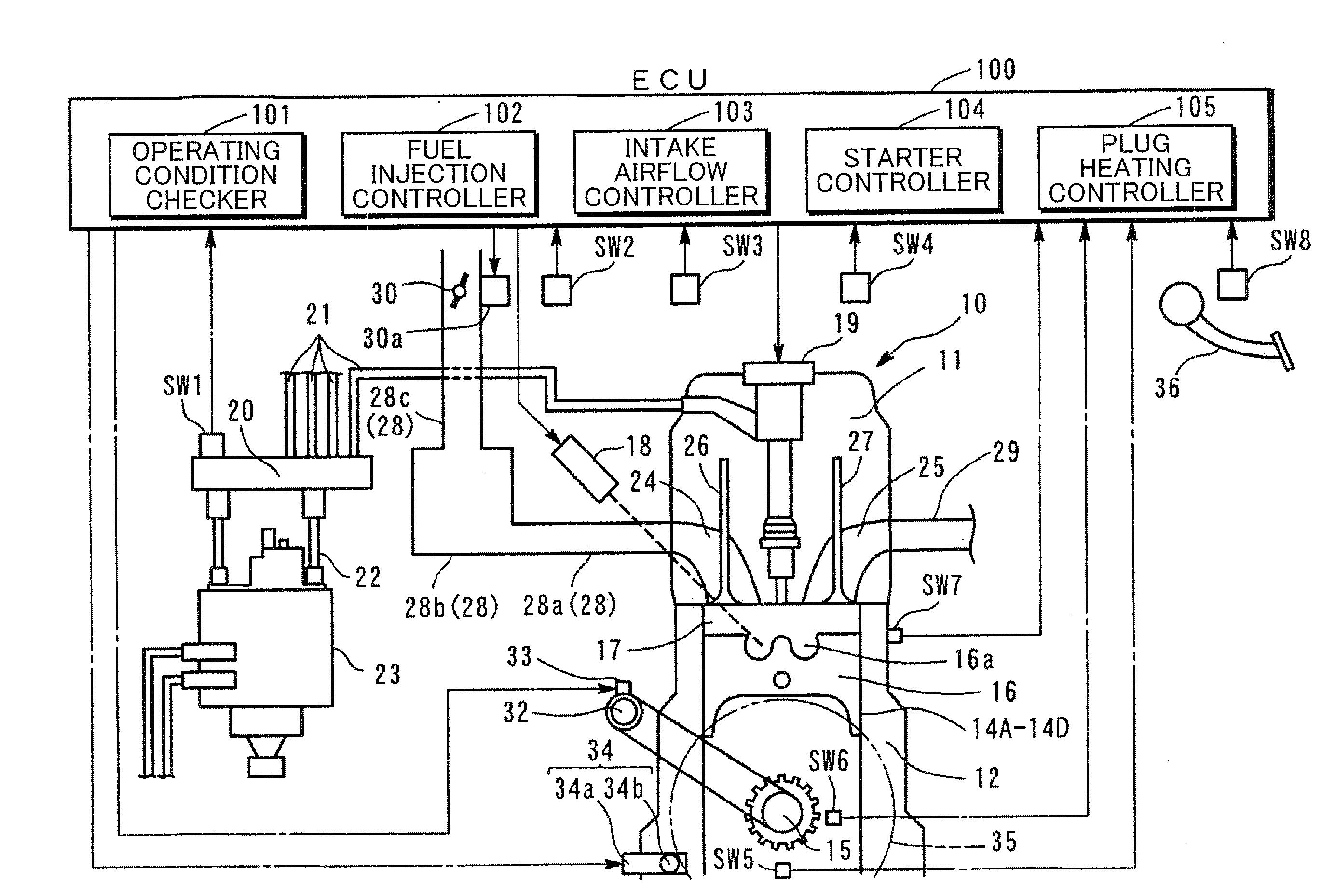
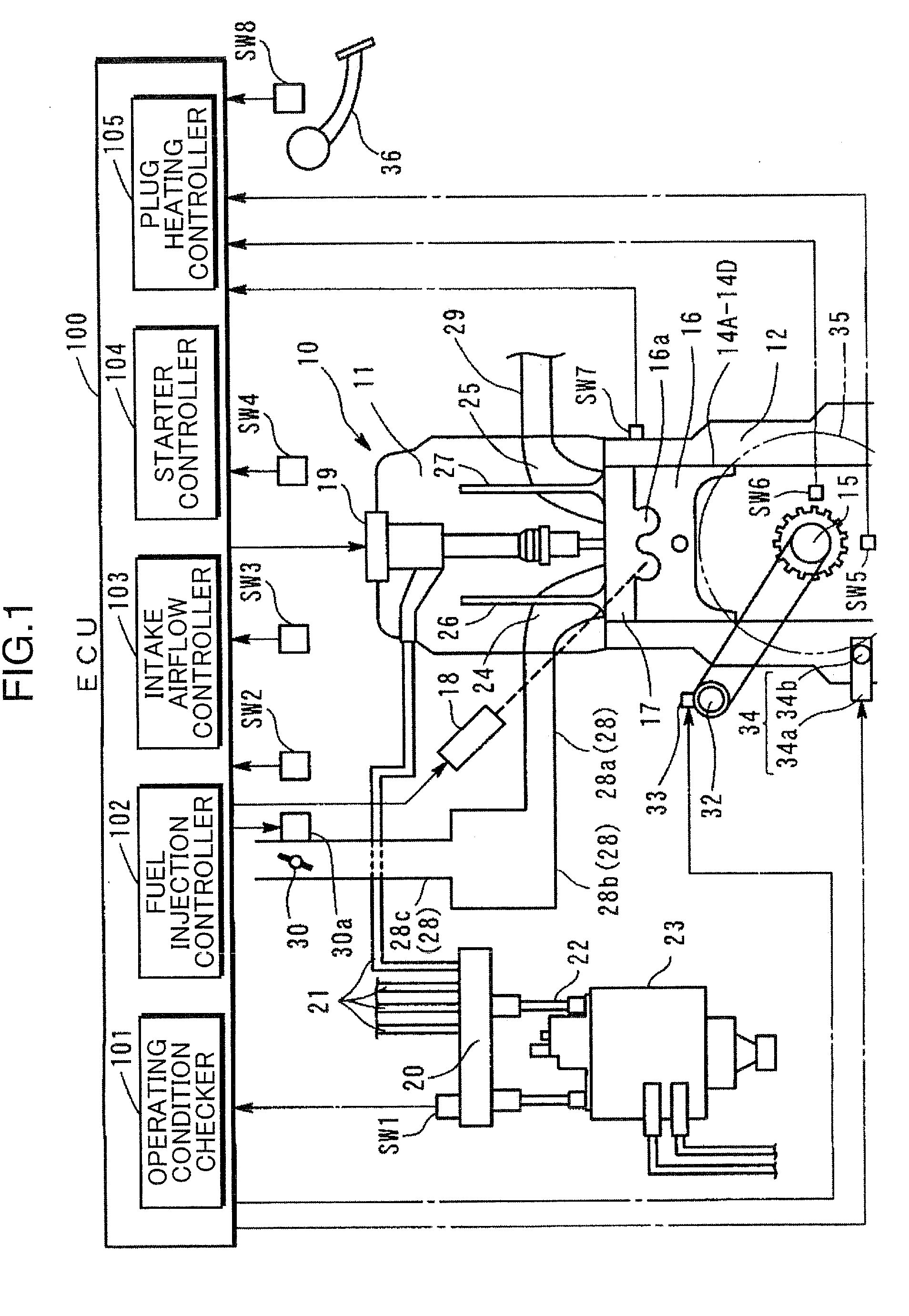
[0020]A preferred embodiment of the present invention is now described in detail with reference to the accompanying drawings. FIG. 1 is a schematic diagram of a four-stroke diesel engine 10 according to the embodiment of the invention.

[0021]As shown in FIG. 1, the engine 10 comprises a cylinder head 11 and a cylinder block 12, in which four cylinders 14A-14D (which may collectively be referred to as the cylinders 14 hereinbelow) are formed. Fitted in the four cylinders 14A-14D are pistons 16 which are joined to a crankshaft 15 by respective connecting rods (not shown). Each of the pistons 16 has a cavity 16a formed in a top surface thereof. There is formed a combustion chamber 17 in each of the cylinders 14A-14D, the combustion chamber 17 being bounded by an inside surface (bottom) of the cylinder head 11 and the cavity 16a formed in the piston 16. The pistons 16 fitted in the individual cylinders 14A-14D move up and down with specific phase differences as the crankshaft 15 rotates....


PUM


Abstract

In a process of automatically stopping a diesel engine upon fulfillment of automatic engine stop conditions, an ECU cuts off fuel injection when the engine speed equals a preset first engine speed N1. The ECU limits the amount of intake air at the first engine speed N1 and, then, increases the amount of intake air at a point in time when the engine speed equals a second engine speed N2, at which point a piston in a cylinder which will be on a compression stroke at engine stop is expected to transfer to a last intake stroke, so that the piston in the compression stroke cylinder at engine stop stops at a point within a specified range closer to the bottom dead center than a piston in a cylinder which will be on an expansion stroke at engine stop.

Description

BACKGROUND OF THE INVENTION[0001]1. Field of the Invention[0002]The present invention relates to a diesel engine system and a method of controlling a diesel engine.[0003]2. Description of the Related Art[0004]There is a general tendency today to employ an automatic stop / restart control system in a diesel engine. As described in Japanese Unexamined Patent Publication No. 2006-46251, for example, an automatic stop / restart control system of a diesel engine stops the engine when prescribed automatic engine stop conditions are satisfied and restarts the automatically stopped engine when prescribed engine restart conditions are satisfied.[0005]For restarting the automatically stopped diesel engine, it is necessary to inject fuel into a cylinder which was in a compression stroke at automatic engine stop to induce self-ignition in the cylinder. A problem often encountered with a diesel engine having an automatic stop / restart feature is deterioration of starting performance which is caused b...

Claims


Application Information

Patent Timeline
IPC IPC(8): F02D45/00
CPCF02D35/026F02D2009/0247F02D41/042F02D41/065F02D41/3827F02D2011/102F02D2041/0092F02D2041/0095F02D2041/389F02N11/0814F02N19/005F02N99/006F02N2019/008F02P19/023Y02T10/48Y02T10/42F02D13/08F02D17/02F02D2009/0245F02D2041/0022F02D41/0002Y02T10/40
Inventor TETSUNO, MASAYUKI
Owner MAZDA MOTOR CORP
Why Eureka
Try Eureka