
Projection display apparatus

a projection display and display device technology, applied in the field of projection display devices, can solve the problems of increasing the cost of projection display devices including sub-power supplies for backups, and the limitation of non-volatile memory data can be rewritten

Active Publication Date: 2009-03-12
CANON KK
View PDF3 Cites 6 Cited by
  • Summary
  • Abstract
  • Description
  • Claims
  • Application Information

AI Technical Summary

Benefits of technology

[0007]It is desirable to provide a projection display apparatus that can reliably store data of a volatile memory in a nonvolatile memory when an external power supply is cut off even if the projection display apparatus does not have a sub-power supply for a backup.
[0008]It is also desirable to provide a projection display apparatus having a sub-power supply for a backup, which can lengthen the backup time and / or that can miniaturize the sub-power supply for a backup.

Problems solved by technology

Such a control is performed since the access speed of the nonvolatile memory is slower than that of the volatile memory, and also the nonvolatile memory may have a limitation on the number of times data can be rewritten.
However, there is a problem when the input power is forced to be cut off before the updated data in the volatile memory are stored in the nonvolatile memory.
However, a projection display apparatus including a sub-power supply for a backup increases in cost since it has the sub-power supply.

Method used


Image

  • Projection display apparatus
  • Projection display apparatus
  • Projection display apparatus

Examples


embodiment 1

[0019]First, Embodiment 1 of the present invention will be described.

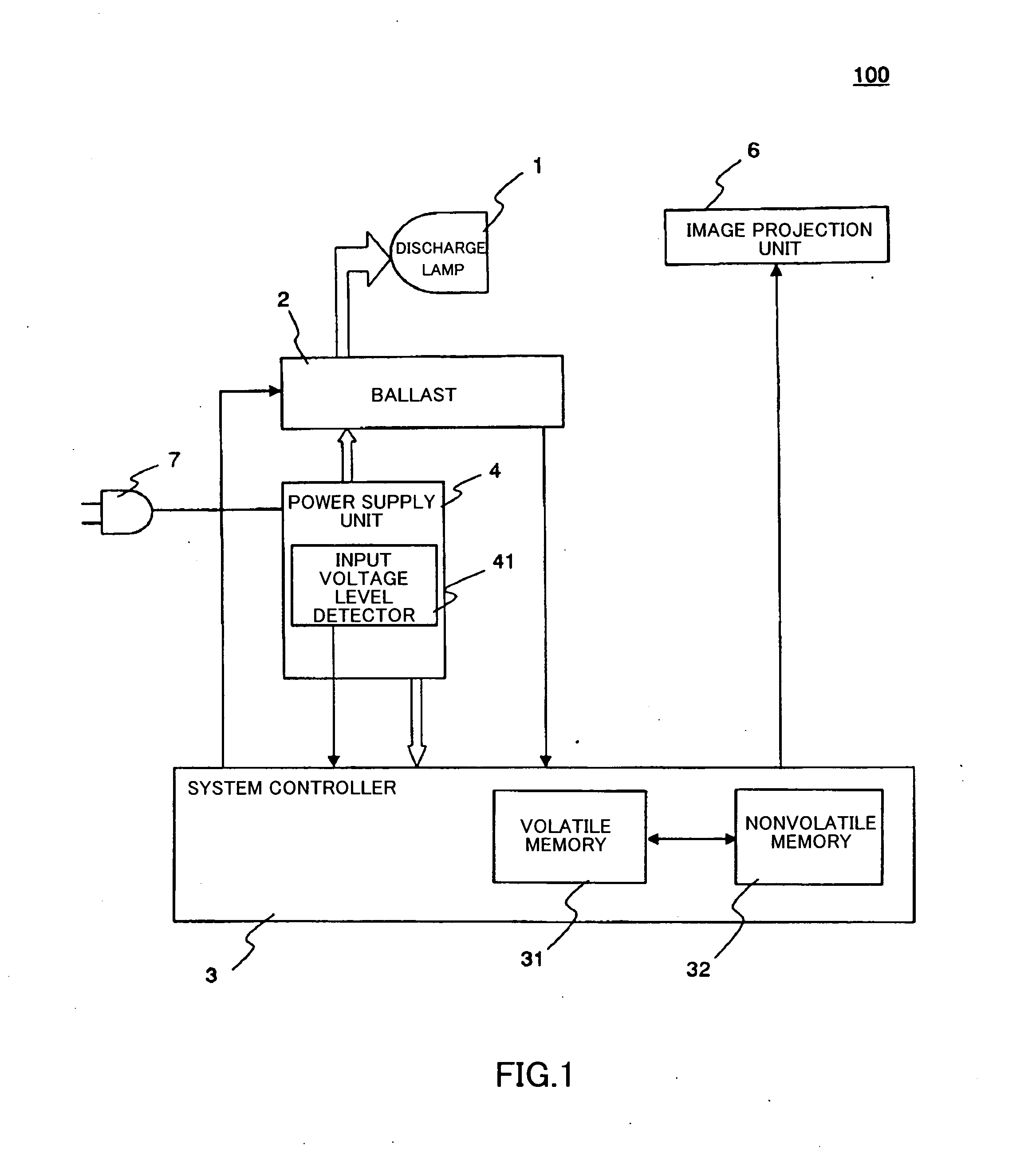
[0020]FIG. 1 shows a block diagram of a projector 100 that is a projection display apparatus of the present embodiment.

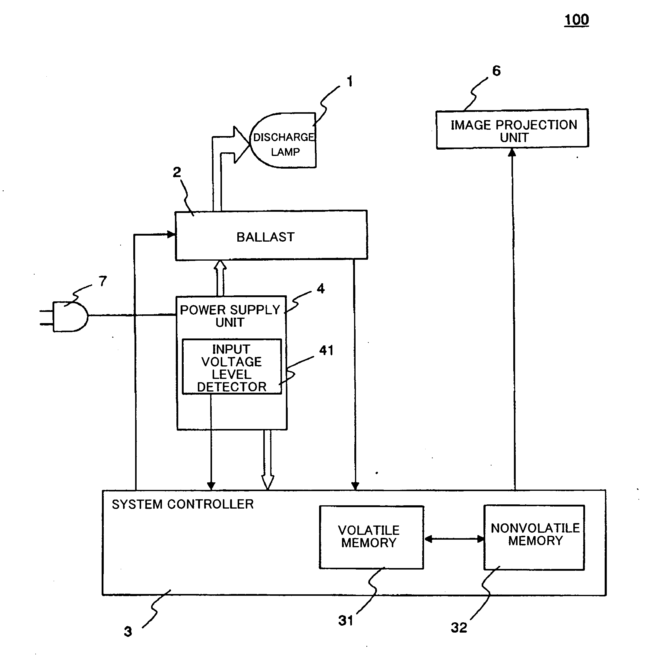
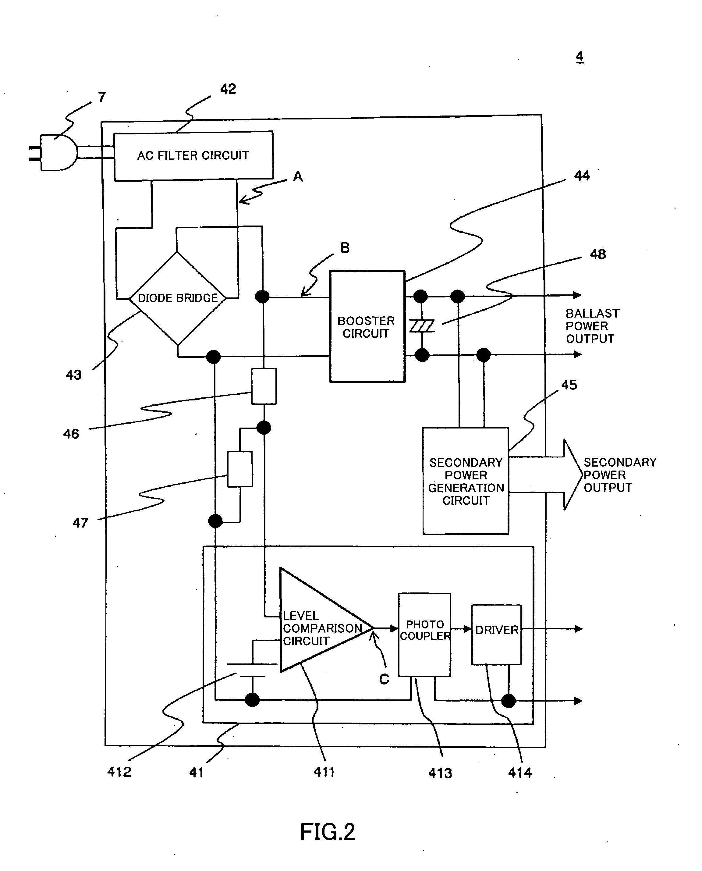
[0021]First, the configuration of the projector 100 will be described. Reference numeral 1 denotes a discharge lamp that is used as a light source of the projector 100. Reference numeral 2 denotes a ballast (a power controller) that performs a lighting control and a constant power control of the discharge lamp 1. The ballast 2 is provided between the discharge lamp 1 and the power supply unit 4 in order to stabilize the power supplied to the discharge lamp 1. Reference numeral 3 denotes a system controller. The system controller 3 performs an output control of a lamp lighting command signal to the ballast 2. The ballast 2 controls the discharge lamp 1 based on the lamp lighting command signal outputted from the system controller 3. The system controller 3 performs a signal processing of projection ...

embodiment 2

[0052]Next, embodiment 2 of the present invention will be described.

[0053]FIG. 7 shows a block diagram of a projector 200 that is a projection display apparatus of the present embodiment. In the present embodiment, the description of the configurations and the operations of embodiment 2 which are the same as that of embodiment 1 will be omitted, and the description will be focused on the configurations and the operations which are different from those of embodiment 1.

[0054]The configuration of the present embodiment is different from that of embodiment 1 in that a switching unit 5 is provided between the system controller 3 and the ballast 2.

[0055]The switching unit 5 is provided as a hardware circuit and includes components such as MOSFETs and transistors. The switching unit 5 controls the transmission of the lamp lighting command signal that is outputted from the system controller 3 to the ballast 2 by its ON / OFF action. In other words, the switching unit 5 passes, or blocks passa...


PUM


Abstract

A projector 100 includes an image projection unit 6 that projects an image using light from a discharge lamp 1, a ballast 2 that controls a supply voltage supplied to the discharge lamp 1, a system controller 3 that controls a command signal outputted to the ballast 2, a volatile memory 31, a nonvolatile memory 32 that stores data stored in the volatile memory 31, and a power supply unit 4 that includes a capacitor 48 used for generating a supply voltage supplied from an external power supply to the ballast 2. The system controller 3 stores the data of the volatile memory 31 in the nonvolatile memory 32 using a voltage generated by accumulated charges of the capacitor 48 when the external power supply is cut off.

Description

BACKGROUND OF THE INVENTION[0001]The present invention relates to a projection display apparatus projecting images using light from a light source, and more particularly to a projection display apparatus that stores data, for example the data of a volatile memory, in a nonvolatile memory when an external power supply is forcibly cut off.[0002]When a projector is used, a user can individually set some operating parameters such as brightness, color, contrast, and languages. Furthermore, the system of the projector updates and retains information such as a period of lighting, the number of lighting, and error information, by itself.[0003]These data are tentatively stored in a RAM (Random Access Memory) that is a volatile memory. The data stored in the volatile memory are collectively stored in an EEPROM (Electrically Erasable Programmable Read Only Memory) or a FLASH-EEPROM that is a nonvolatile memory at regular time intervals. Such a control is performed since the access speed of the...

Claims


Application Information

Patent Timeline
Patent Type & Authority Applications(United States)
IPC IPC(8): G11C5/14G03B21/14
CPCH04N5/63H04N9/3197H04N9/3155H04N5/7416
Inventor YASUDA, HITOSHI
Owner CANON KK
Learn More