
Bypass turbomachine with reduction of jet noise

Active Publication Date: 2009-03-12
SN DETUDE & DE CONSTR DE MOTEURS DAVIATION S N E C M A
View PDF4 Cites 10 Cited by
  • Summary
  • Abstract
  • Description
  • Claims
  • Application Information

AI Technical Summary

Benefits of technology

[0013]The present invention seeks to remedy the above-mentioned drawbacks by proposing a simple and effective configuration for reducing jet noise by blowing air, and that is suitable for installing in a turbomachine having movable thrust reverser covers in its nacelle.
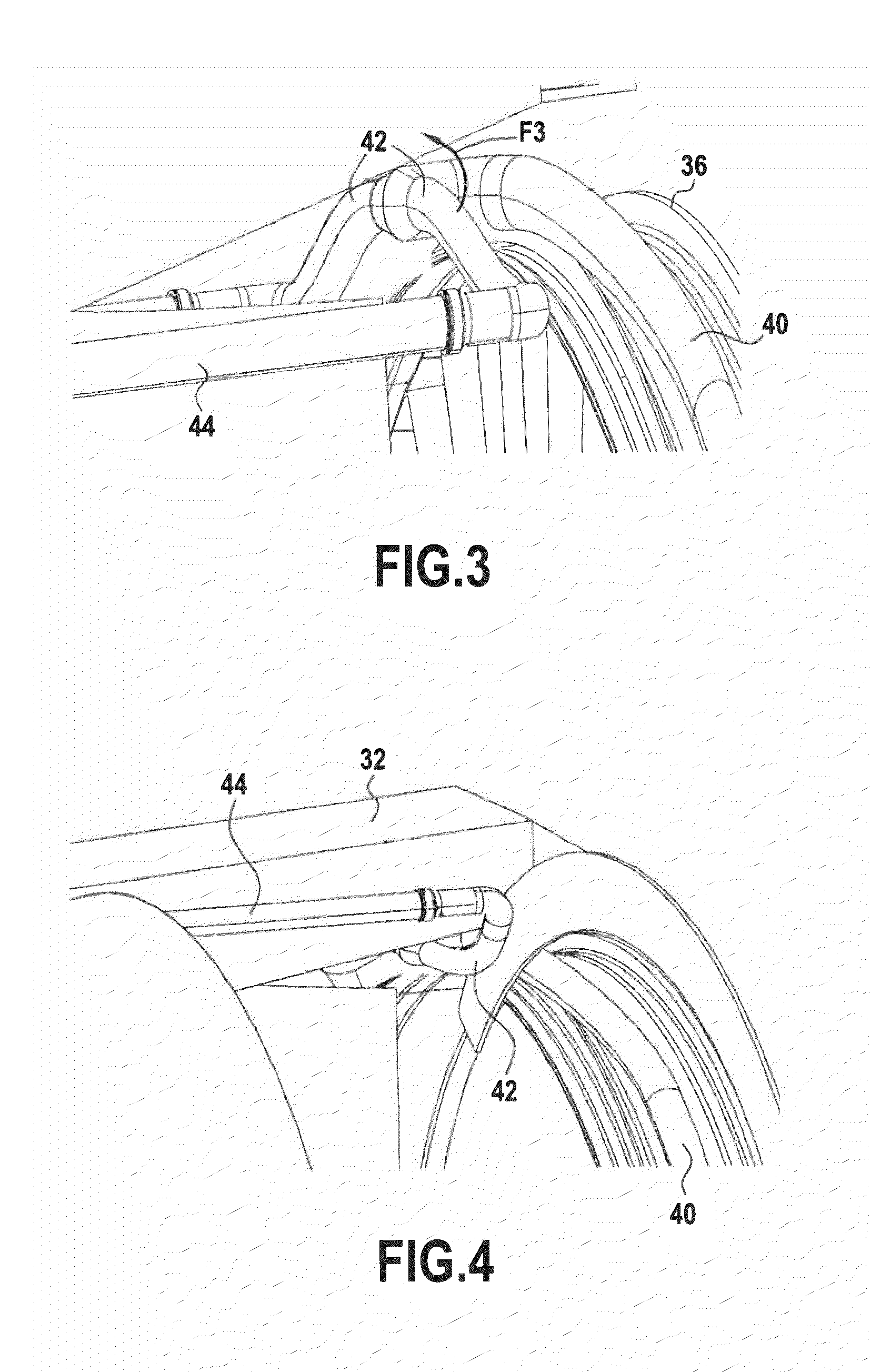
[0021]Under such circumstances, each air diffusion pipe is made of a flexible material so as to make it easier to deform the air diffusion pipe.
[0022]Preferably, each air injection pipe includes an endpiece that is conical so as to make it easier to couple and uncouple the air takeoff pipe.

Problems solved by technology

Nowadays, sound pollution has become one of the major concerns of engine manufacturers, since they are becoming ever more confronted with the noise nuisance produced by their turbomachines.
The sources of noise in a turbomachine are numerous, however it has been found that the jet noise at the outlet from the nozzle is the predominant noise, particularly while an airplane is taking off.
Certification authorities are becoming more and more demanding concerning noise emissions from turbomachines, and engine manufacturers are being required to reduce the noise produced by their turbomachines, and in particular the jet noise at the nozzle outlet.
Unfortunately, the presence of these longitudinally-movable covers manifestly raises a problem of conveying air from the point where it is taken off in the turbomachine all the way to the trailing edge of the nacelle from which the air is to be blown.
Furthermore, when the nacelle of such a turbomachine also includes two maintenance covers in its central portion that are suitable for pivoting about hinges that are parallel to the longitudinal axis of the turbomachine, the circuit for delivering the air that has been taken off is even more complicated to provide.

Method used


Image

  • Bypass turbomachine with reduction of jet noise
  • Bypass turbomachine with reduction of jet noise
  • Bypass turbomachine with reduction of jet noise

Examples


Embodiment Construction

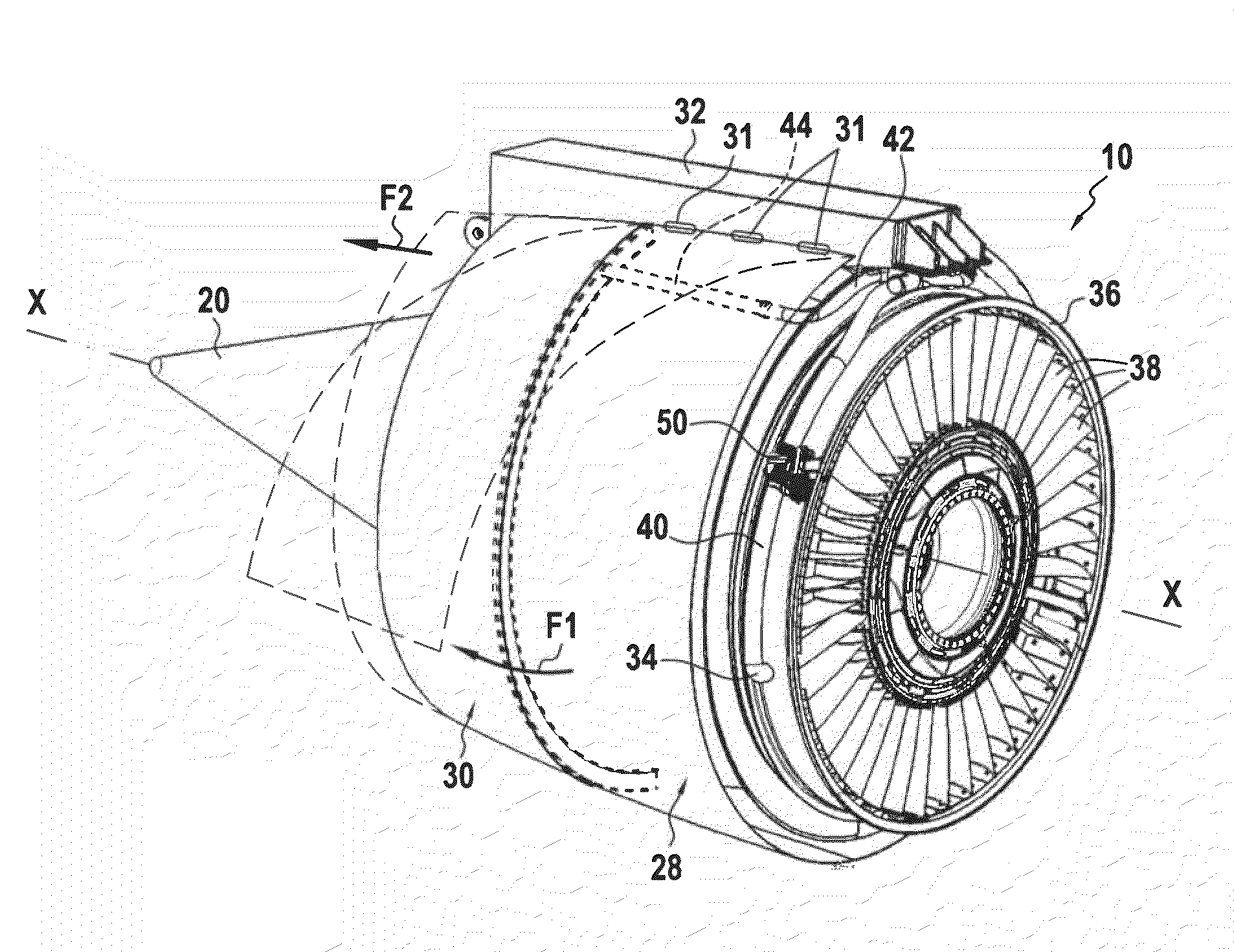
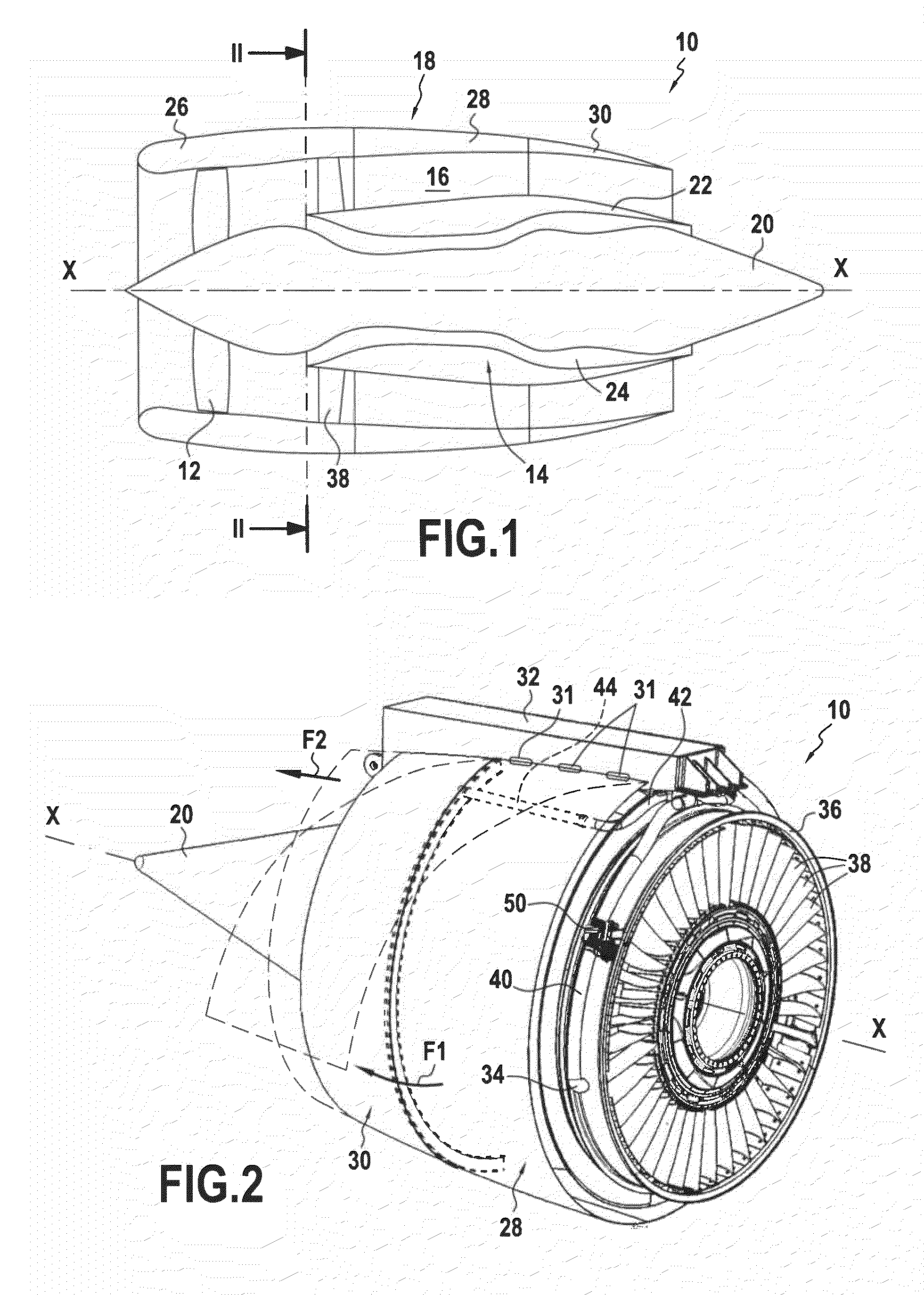
[0029]The turbomachine 10 of longitudinal axis X-X shown in FIG. 1 is of the bypass type.

[0030]In well-known manner, it comprises in particular a fan 12 that is driven by a gas generator 14, and an annular fan channel 16 that is defined on the outside by a nacelle 18.

[0031]The turbomachine 10 also comprises a central annular body 20 centered on the longitudinal axis X-X, and a primary annular fairing 22 disposed coaxially around the central body 20 so as to co-operate therewith to define a primary annular channel 24 for passing a flow of gas from the gas generator 14.

[0032]Going from upstream to downstream in the flow direction of the stream inside the turbomachine, the nacelle 18 comprises an annular air inlet sleeve 26, two maintenance covers 28 of semi-cylindrical shape (only one of them is visible in FIG. 2), and two thrust reverser covers 30 likewise in the form of half-cylinders (only one of them is visible in FIG. 2).

[0033]The maintenance covers 28 are situated in the central...


PUM


Abstract

In a bypass turbomachine, at least one air takeoff orifice is provided in the primary channel, said orifice leading to an air takeoff pipe housed inside an air inlet sleeve of the nacelle. The air takeoff pipe opens out in the vicinity of the pylon into two air diffusion pipes each secured to a respective maintenance cover, each air diffusion pipe opening out into an air injection pipe secured to a thrust reverser cover and itself opening out to the outside of the nacelle via the trailing edge thereof, each air injection pipe being suitable for uncoupling from the corresponding air diffusion pipe when the corresponding thrust reverser cover slides downstream.

Description

BACKGROUND OF THE INVENTION[0001]The present invention relates to reducing the jet noise from a bypass turbomachine nozzle. The invention relates more precisely to a bypass turbomachine with reduced jet noise.[0002]Nowadays, sound pollution has become one of the major concerns of engine manufacturers, since they are becoming ever more confronted with the noise nuisance produced by their turbomachines. The sources of noise in a turbomachine are numerous, however it has been found that the jet noise at the outlet from the nozzle is the predominant noise, particularly while an airplane is taking off.[0003]Certification authorities are becoming more and more demanding concerning noise emissions from turbomachines, and engine manufacturers are being required to reduce the noise produced by their turbomachines, and in particular the jet noise at the nozzle outlet.[0004]Typically, a bypass turbomachine has a fan driven by a gas generator, a primary annular channel for passing a primary gas...

Claims


Application Information

Patent Timeline
IPC IPC(8): F02K1/34F02K3/02
CPCF02K1/34F05D2260/96F02K1/72F02K1/46
Inventor BEUTIN, BRUNO ALBERTDERENES, JACKY RAPHAEL MICHELEICHSTADT, FREDERIC PAULVUILLEMIN, ALEXANDRE ALFRED GASTON
Owner SN DETUDE & DE CONSTR DE MOTEURS DAVIATION S N E C M A
Learn More