
Heat exchange reformer unit and reformer system

a heat exchange and reformer technology, applied in the direction of combustible gas production, sustainable manufacturing/processing, chemical/physical/physicochemical processes, etc., can solve the problem of limiting the improvement of the reforming efficiency of the system, and achieve excellent heat exchange efficiency between the heating section and the reforming section.

Inactive Publication Date: 2009-03-12
TOYOTA JIDOSHA KK
View PDF7 Cites 18 Cited by
  • Summary
  • Abstract
  • Description
  • Claims
  • Application Information

AI Technical Summary

Benefits of technology

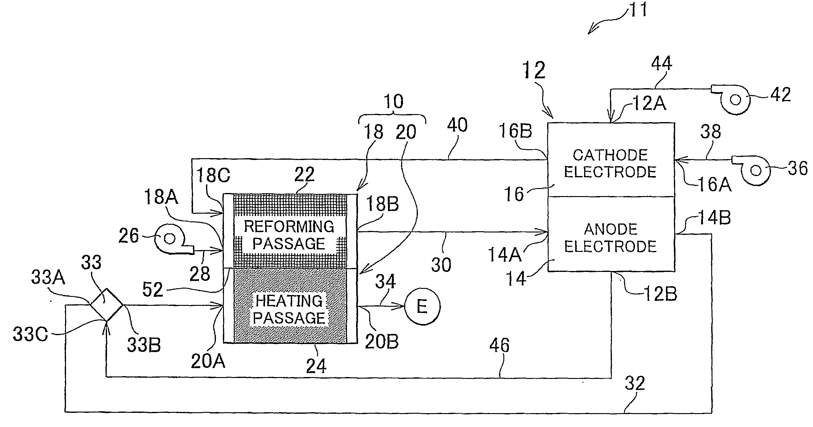
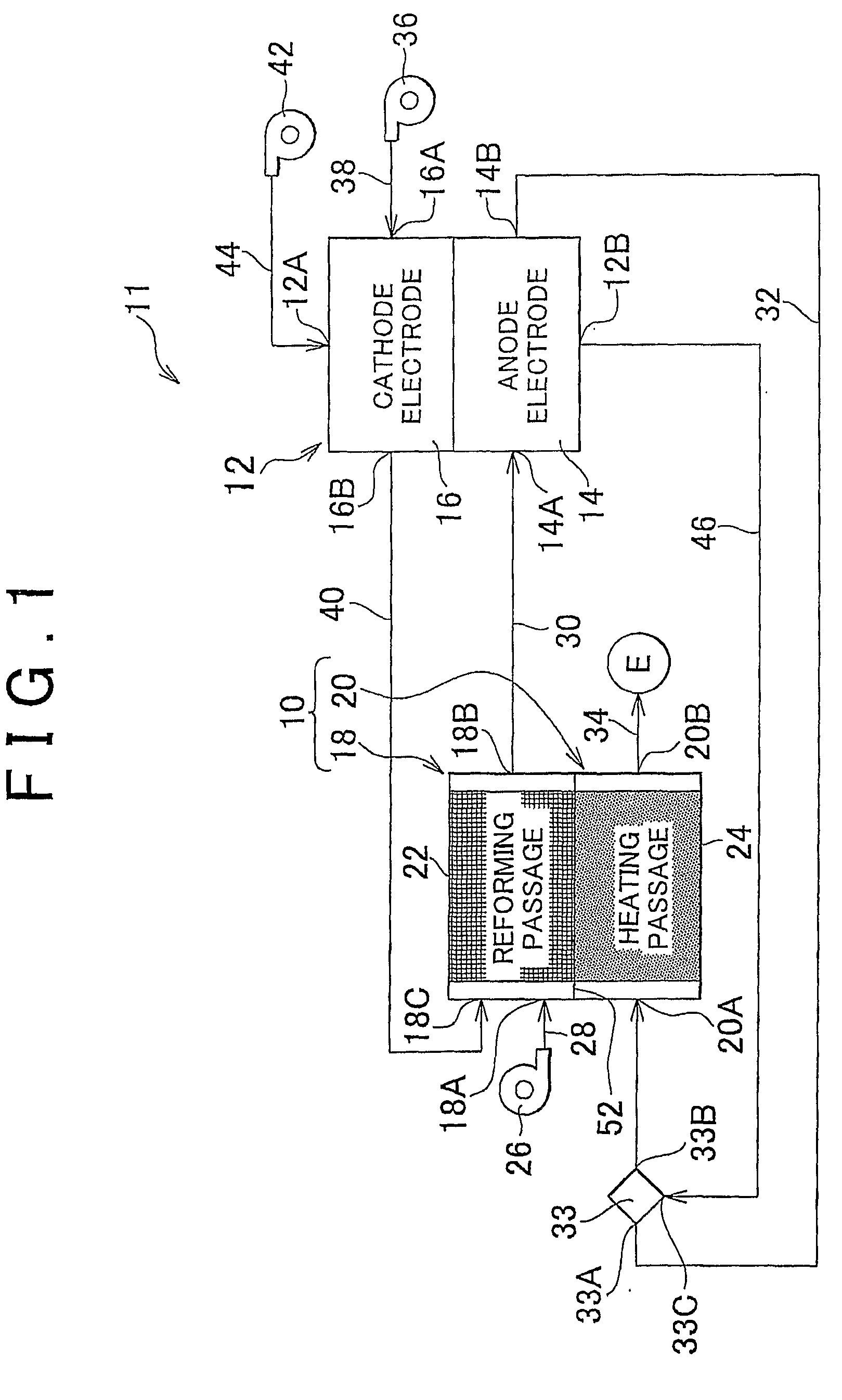
[0006]The present invention provides a heat exchange reformer unit of which the efficiency of heat exchange between a heating section and a reforming section is excellent. The present invention also provides a heat exchange reformer unit and a reformer system, which make it possible to improve reforming efficiency.

Problems solved by technology

In addition, because, in a fuel reformer, the difference between the reaction velocity of the reforming reactions (mainly, steam reforming reaction) in the reforming passages and the reaction velocity of the combustion reactions in the combustion passages is large, that is, the difference in the amount of reaction per volume between the reforming passages and the combustion passages is large, there has been a limit to the improvement in the reforming efficiency of the system when the configuration is adopted in which the reforming passages and combustion passages are merely alternately formed in the stacking direction as described above.

Method used


Image

  • Heat exchange reformer unit and reformer system
  • Heat exchange reformer unit and reformer system
  • Heat exchange reformer unit and reformer system

Examples


third embodiment

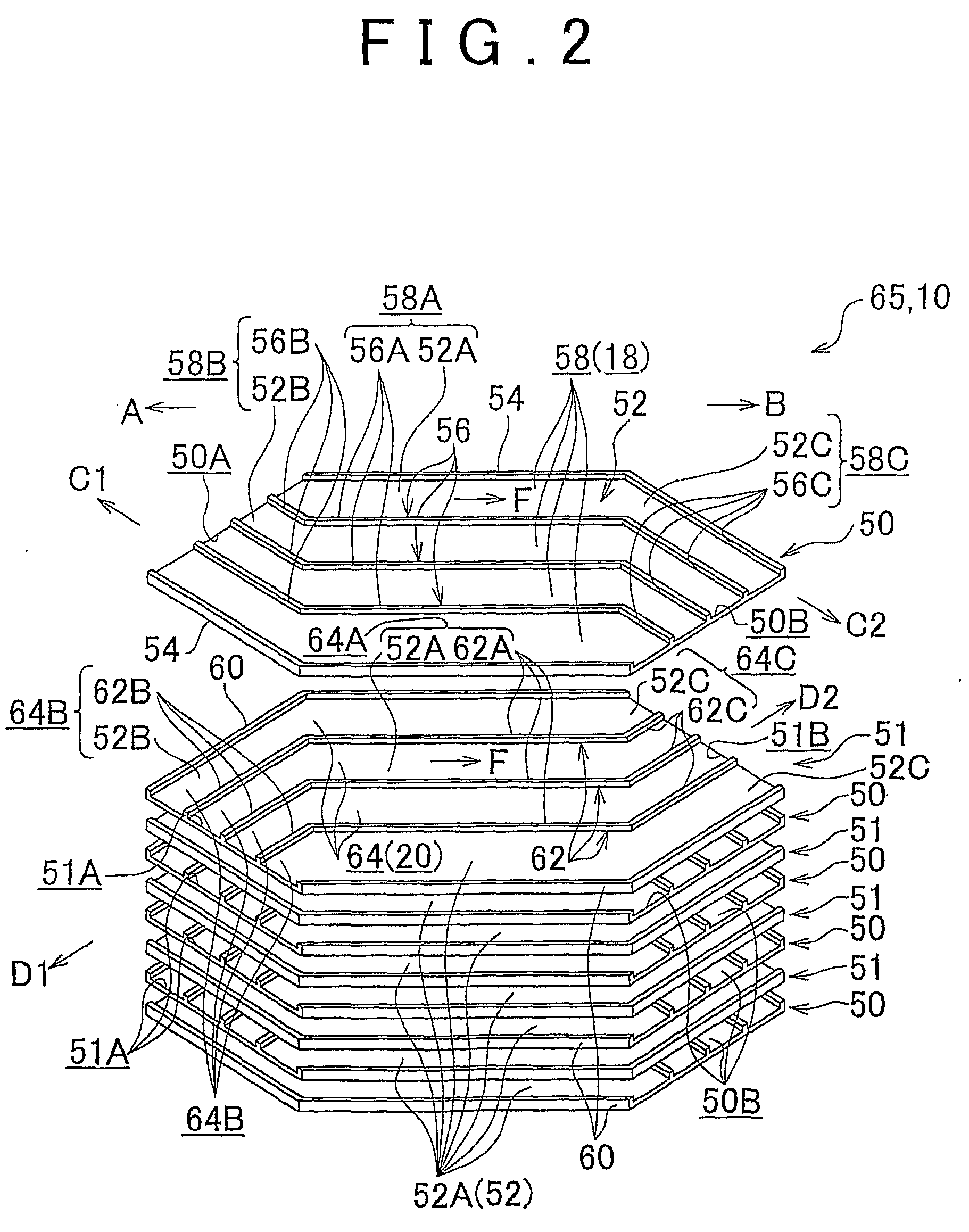
[0149]FIG. 15A shows a heat exchange reformer unit 80 according to a third embodiment in a front view in section corresponding to FIG. 8A. As shown in FIG. 15A, the heat exchange reformer unit 80 differs from the heat exchange reformer unit 10, which includes the multilayer core unit 65 in which two layers of the reforming passages 18 are stacked per one layer of the combustion passage 20, in that the heat exchange reformer unit 80 includes a multilayer core unit 82 in which three unit plate members 50 (three layers of the reforming passages 18) are stacked per one unit plate member 51 (one layer of the combustion passage 20).

[0150]Specifically, in the multilayer core unit 82, three layers of the reforming passages 18 are disposed between a pair of the combustion passages 20, as shown in FIG. 15B, by stacking the units, in each of which three unit plate members 50 are stacked on the same side of one unit plate member 51. Accordingly, in the multilayer core unit 82, one layer of the ...

fourth embodiment

[0155]FIG. 16A shows a front view in section of a heat exchange reformer unit 90 according to a fourth embodiment. FIG. 16B shows a plan view of the reforming passage 18 (combustion passage 20) constituting the heat exchange reformer unit 90. As shown in these figures, the heat exchange reformer unit 90 differs from the heat exchange reformer unit 80 in including a multilayer core unit 94 in which such unit plate members 50 and 51 as described below are stacked. Specifically, in the unit plate member 50, heat transfer-supporting ribs 92, which constitutes heat transfer-promoting portions, are provided in a standing condition between the end portions of the standing walls 56 on the gas inlet 50A-side thereof, and in unit plate members 51, heat transfer-supporting ribs 92, which constitutes heat transfer-promoting portions, are provided in a standing condition between the end portions of the standing walls 62 on the gas inlet 51A-side thereof.

[0156]In the fourth embodiment, the heat t...

fifth embodiment

[0160]FIG. 19A shows a heat exchange reformer unit 100 according to a fifth embodiment in a front view in section. FIG. 19B shows the reforming passages 18 (combustion passages 20) constituting the heat exchange reformer unit 100 in a plan view. As shown in these figures, the heat exchange reformer unit 100 differs from the heat exchange reformer unit 80 in including a multilayer core unit 104 in which such unit plate members 50 and 51 as described below are stacked. Specifically, in the unit plate members 50 and 51, end portions of the standing walls 56 on the gas inlet 50A-side, and end portions of the standing walls 62 on the gas inlet 51A-side are formed into heat transfer-supporting thick portions 102 as heat transfer-promoting portions, which are thicker than the remaining portions of the standing walls 56 and 62.

[0161]The heat transfer-supporting thick portions 102 are set substantially corresponding to the reaction field in which the combustion reactions mainly occur in the ...


PUM

PropertyMeasurementUnit
temperaturesaaaaaaaaaa
surface areaaaaaaaaaaa
total volumeaaaaaaaaaa

Abstract

In a heat exchange reformer unit, a reforming passage supporting reform catalyst for inducing reforming reactions and a combustion passage supporting oxidizing catalyst for combustion are disposed adjacent to each other with a plate portion interposed therebetween. Heat-exchanging passages of the reforming passage that produce reformate gas that contains hydrogen from supplied reformation material, and heat-exchanging passages of the combustion passage that supply heat, which is generated by catalytically burning supplied fuel, to the reforming passage constitute a parallel-flow heat exchanger. Reformation material guide passages for introducing reformation material into the heat-exchanging passages in a predetermined direction, and mixed gas guide passages for introducing fuel into the heat-exchanging passages in a direction intersecting the gas flow direction in the reformation material guide passages, are provided upstream of the heat-exchanging passages in a gas flow direction.

Description

BACKGROUND OF THE INVENTION[0001]1. Field of the Invention[0002]The present invention relates to a heat exchange reformer unit in which reforming reactions are caused by which reformate gas that contains hydrogen is obtained from reformation material, such as hydrocarbon, with heat supplied from a heating section to a reforming section. The present invention also relates to a reformer system including such a heat exchange reformer unit.[0003]2. Description of the Related Art[0004]A cross-flow heat exchange fuel reformer is available in which reforming passages for producing gas that contains hydrogen by reforming hydrocarbon material and combustion passages for burning fuel gas to supply heat, which is used in reforming reactions, to the reforming passages are alternately formed (see Japanese Patent Application Publication No. 2004-244230 (JP-A-2004-244230)). JP-A-2004-244230 describes a technology for setting a region in which catalyst is not supported between plates so that the di...

Claims


Application Information

Patent Timeline
Patent Type & Authority Applications(United States)
IPC IPC(8): C10J3/68C10J1/207
CPCB01J19/0093C01B2203/141B01J2219/00783B01J2219/00822B01J2219/00824B01J2219/00835B01J2219/00873B01J2219/1928B01J2219/2453B01J2219/2458B01J2219/2465B01J2219/247B01J2219/2479B01J2219/2481B01J2219/2485B01J2219/2486B01J2219/2487C01B3/384C01B2203/0233C01B2203/066C01B2203/0811C01B2203/0822C01B2203/0827C01B2203/12B01J19/249Y02P20/10
Inventor WAKASUGI, TOMOHISASHIMAZU, TAKASHIKIMURA, KENJI
Owner TOYOTA JIDOSHA KK
Learn More