Engine system with reformer

a technology of engine system and reformer, which is applied in the direction of machines/engines, mechanical equipment, combustion air/fuel air treatment, etc., can solve the problems of reducing the reforming efficiency and the difficulty of increasing the reforming efficiency, and achieve excellent system efficiency, improve the reforming efficiency of the reformer, and recover waste heat and the effect of combustion efficiency

Inactive Publication Date: 2013-12-03
HITACHI LTD
View PDF20 Cites 2 Cited by
  • Summary
  • Abstract
  • Description
  • Claims
  • Application Information

AI Technical Summary

Benefits of technology

[0009]According to the present invention, an engine system, in which an amount of recovered waste heat and a combustion efficiency of an engine are improved by improving a reforming efficiency of a reformer, and thereby resulting in an excellent system efficiency, can be provided.

Problems solved by technology

Therefore, it is difficult to increase the reforming efficiency.
For this reason, there is a problem that a combustion temperature falls at the time of engine combustion, an exhaust gas temperature falls, resulting in a decrease in reforming efficiency.

Method used


Image

  • Engine system with reformer
  • Engine system with reformer
  • Engine system with reformer

Examples


Embodiment Construction

[0026]Hereinafter, an embodiment of the present invention will be explained with reference to the accompanying drawings.

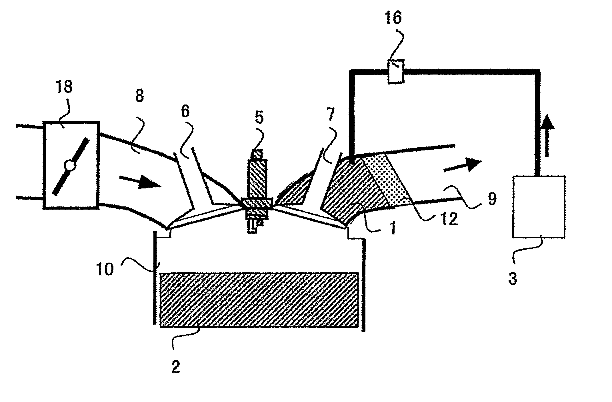
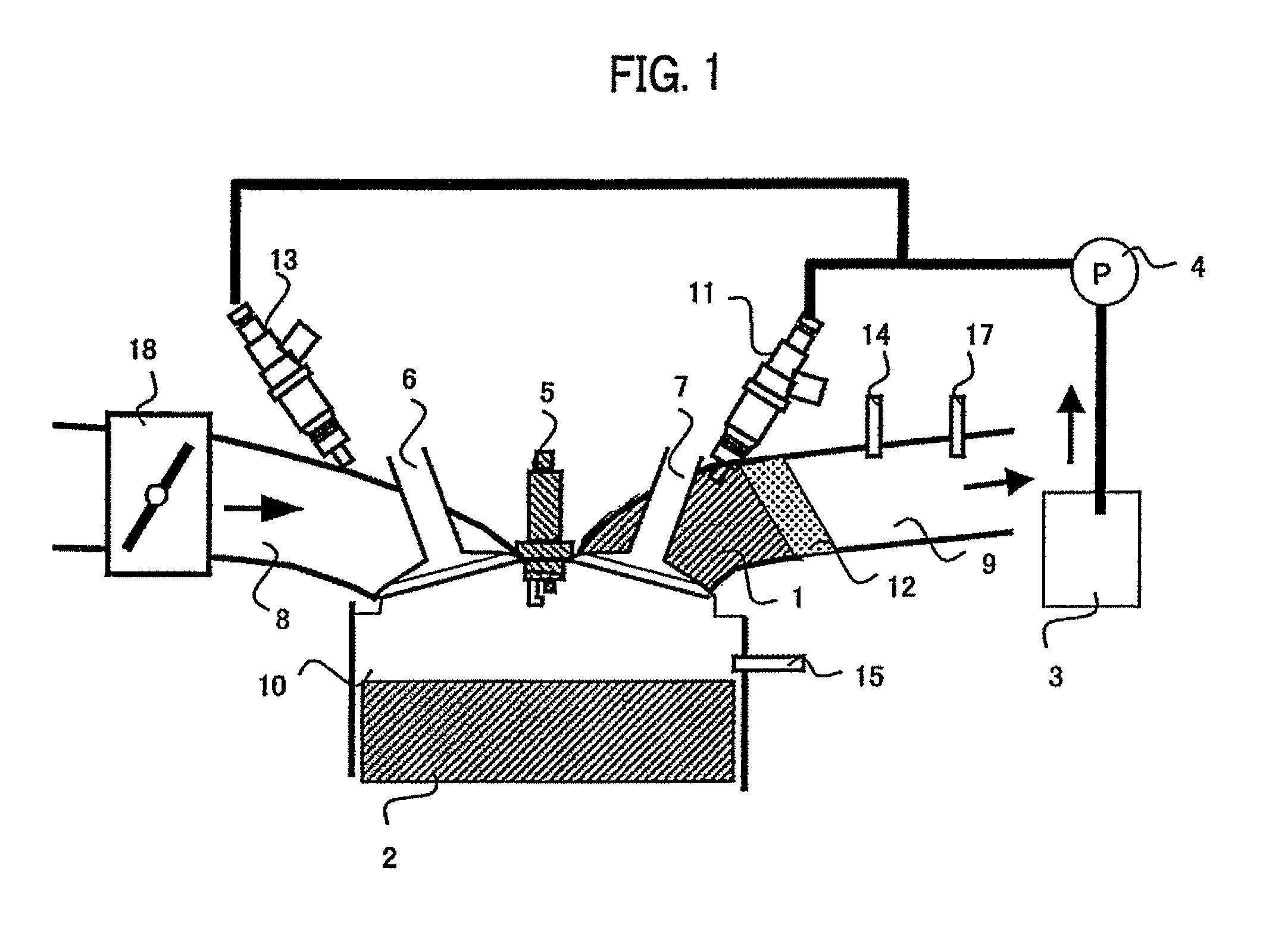
[0027]FIG. 1 is a first configuration diagram of this system. A reformer 1 is installed in an engine head in the vicinity of an exhaust valve 7 of an exhaust pipe 9, or at the exhaust pipe immediately behind the engine head. A pre-reformed fuel 3 is supplied to the reformer 1 from a pre-reformed fuel tank 3 via a pre-reformed fuel supply adjustment unit 11. Here, the reformer 1 is installed adjacent to an engine combustion chamber via an exhaust valve 7 which also functions as a reformed fuel supply adjustment unit. According to this configuration, a combustion gas right after exhausted from an engine cylinder 10 is supplied to the reformer 1, resulting in supply of an engine exhaust heat at high temperature.

[0028]The exhaust valve 7 also functions as a reformed fuel supply adjustment unit to supply the reformed fuel into the engine cylinder 10. Normally, since an ...


PUM


Abstract

Disclosed is an engine system with a reformer, the engine system comprising a reformer and driving an engine using, as a fuel, a reformed fuel produced by reforming pre-reformed fuel with the reformer, in which the reformer is connected with both a pre-reformed fuel supply adjustment unit which adjusts the amount of the pre-reformed fuel supplied to the reformer and a reformed fuel supply adjustment unit which adjusts the amount of reformed fuel supplied to the engine, and the reformer is installed adjacent to the engine combustion chamber via the reformed fuel supply adjustment unit.

Description

FIELD OF THE INVENTION[0001]The present invention relates to an engine system with a reformer.BACKGROUND OF THE INVENTION[0002]In a system in which a fuel is reformed by an endothermic reaction so that a reformed gas including hydrogen, etc. is produced to be supplied to an engine as a fuel, by reforming the fuel in the endothermic reaction using an engine waste heat, a waste heat is recovered, and an improvement in efficiency is expected. Also, when a hydrocarbon fuel, such as gasoline, etc., is reformed so as to supply a reformed gas including hydrogen to the engine, a pumping loss reduction, a combustion efficiency improvement, and a combustion rate improvement are enabled, and an improvement in efficiency of the engine is expected. When the reformer is attached to an exhaust pipe of the engine, an exhaust gas temperature of the engine varies according to an operating status of the engine. Therefore, according to conditions, a reforming efficiency varies. Also, when a gas includi...

Claims


Application Information

Patent Timeline
Patent Type & Authority Patents(United States)
IPC IPC(8): F02B75/20F02B43/08F02B43/00
CPCC01B3/38C01B3/382F02M27/02F02M31/08C01B2203/0233C01B2203/1023C01B2203/1041C01B2203/1047C01B2203/1052C01B2203/1064C01B2203/107C01B2203/1082C01B2203/1247C01B2203/148C01B2203/1604Y02T10/126Y02T10/12
Inventor SHIMADA, ATSUSHIISHIKAWA, TAKAOSANO, TADASHI
Owner HITACHI LTD
Why Eureka
Try Eureka