Light-polarizing article and process for making same

Inactive Publication Date: 2009-03-05
CORNING INC
View PDF6 Cites 22 Cited by
  • Summary
  • Abstract
  • Description
  • Claims
  • Application Information

AI Technical Summary

Benefits of technology

[0091]One or more embodiments of the present invention have one or more of the following advantages. (1) Use of a polymeric template, in particular DNA for which well known means for preparing structures having specific, controllable chemical and size and shape characteristics are available, can provide well defined aspect ratio organic and inorganic templated materials that are not easily obtainable by other means. (2) A broad range of metals and optically active organic structures having a range of polarization properties are associable with the DNA templates, making possible a range of polarization wavelengths. (3) The density of the templated material on a surface is controllable by dilution or by multilayered processes. (4) The templated material can be readily aligned on a surface by a number of means, prior to encapsulation in glass. This results in more efficient particle alignment (and more efficient polarization), in contrast to the current process of post encapsulation alignment of metal particles by glass drawing. (5) Encapsulation can make the nanotemplated optically modified surface stable to environmental stresses such as heat and photochemical and chemical damage. (6) The templating / encapsulation process may be used to prepare structures with additional and / or composite optical properties by assembling polarizing films in series. These can include cross polarizers and negative refractive index materials, or complex admixtures of optical properties such as filter plus cross polarizer combinations. (7) Polarcor™ products currently use either silver or copper metal particles which can be limiting in spectral selection. By facilitating the production of nanoparticles from a range of metals and with a range of aspect ratios the process of this invention greatly expands the range of spectral selection—particularly in the blue region where practical solutions have been sought for some time.

Problems solved by technology

However, this crystal is seldom used as a polarizer, since the dichroic effect is strongly wavelength dependent and the crystal appears colored.
They demand expensive equipment and tight process control.

Method used


Image

  • Light-polarizing article and process for making same
  • Light-polarizing article and process for making same
  • Light-polarizing article and process for making same

Examples


example

Preparation of a Polarizer

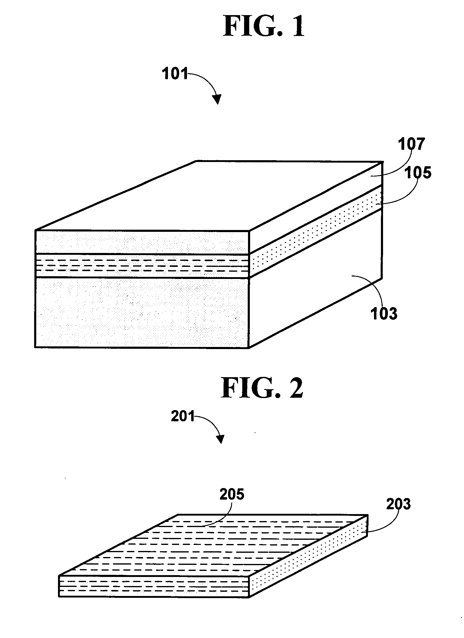
[0199]The selection of aspect ratio for a metal based polarizer depends on the wavelength of light to be polarized and the metal (or combination metals) that is doing the polarization. For a polarizer using a silver nanorod we would require an aspect ratio of 1:5 (width to length aspect ratio). Knowledge of the extent of DNA metallization for each process used is required to ensure the correct aspect ratio. For the metal adduct metallization technique a DNA duplex that is roughly 10 nm long is used assuming each metallization grew to about 2 nm. The base pair length calculation is 10 nm divided by 0.334 nm / base or 30 base pair long duplex. Such DNAs are easily made synthetically however procurement using purification techniques for raw extracts also are possible such as HPLC, centrifugation and electrophoresis. If other metallization techniques were chosen whose particle growth or size or templated size exceeded 2 nm then longer duplex DNAs is required. For...


PUM

PropertyMeasurementUnit
Widthaaaaaaaaaa
Widthaaaaaaaaaa
Nanoscale particle sizeaaaaaaaaaa

Abstract

A process wherein a polymer, such as DNA, having a defined chemical composition and size is used to template the alignment of polarizing species, such as optically active organic dyes or metal nanoparticles having defined compositional characteristics and / or size and shape characteristics, on a surface to manufacture a thin film polarizer; a process where metal nanorods are aligned on a substrate surface or inside a substrate to make a polarizer; and a polarizer thus made. Multi-layered polarizing structure can be created by using the process of the present invention.

Description

TECHNICAL FIELD[0001]The present invention relates to light-polarizing articles and process for making the same. In particular, the present invention relates to light-polarizing articles comprising orderly distributed light-polarizing species on or within a substrate and process for making such light-polarizing article by using an organic templating material or metal nanorods. The present invention is useful, e.g., in making light polarizers having desired polarizing properties in a wide range of wavelength.BACKGROUND[0002]A polarizer is a device that converts an unpolarized or mixed-polarization beam of electromagnetic waves (e.g., light) into a beam with a single polarization state (usually, a single linear polarization). Polarizers are used in many optical techniques and instruments, and polarizing filters find applications in photography and liquid crystal display technology.[0003]The simplest polarizer in concept is the wire-grid polarizer, which consists of a regular array of ...

Claims


Application Information

Patent Timeline
IPC IPC(8): G02B5/30
CPCG02B5/3058C03C14/002C03C2214/08G02B5/3075
Inventor O'MALLEY, SHAWN MICHAEL
Owner CORNING INC
Why Eureka
Try Eureka