Optical scanning device and image forming apparatus

a scanning device and optical scanning technology, applied in the field of optical scanning, can solve the problems of deteriorating the optical performance of the optical scanning device, the inability of the phase shifter to perform wave-front control, and the inability to achieve the effect of wave-front control,

Inactive Publication Date: 2009-03-05
RICOH KK
View PDF15 Cites 27 Cited by
  • Summary
  • Abstract
  • Description
  • Claims
  • Application Information

AI Technical Summary

Benefits of technology

[0015]It is an object of the present invention to at least

Problems solved by technology

This is an inevitable issue that needs to be addressed when the wave properties of the light are subjected to geometric aberration correction.
In other words, if geometric aberration occurs due to temperature fluctuation or positional errors while installing components in an optical scanning device, then the phase shifter cannot perform wave-front control.
That can lead to deterioration in the optical performance of the optical scanning device.
However, following problems occur with respect to such integrated diffractive optical elements.
Firstly, it is difficult to process and mold an integrated configuration of a multistep structure and a two-step structure and the level difference in each orbicular zone is different.
In such a case, it is difficult to independently adjust an integrated diffractive optical element that also has refractive properties and can perform wave-front control.
Otherwise, there is a possibility of hampering the degree of freedom for adjusting the other optical elements.

Method used


Image

  • Optical scanning device and image forming apparatus
  • Optical scanning device and image forming apparatus
  • Optical scanning device and image forming apparatus

Examples


Embodiment Construction

[0035]Exemplary embodiments of the present invention are described in detail below with reference to the accompanying drawings. The present invention is not limited to these exemplary embodiments.

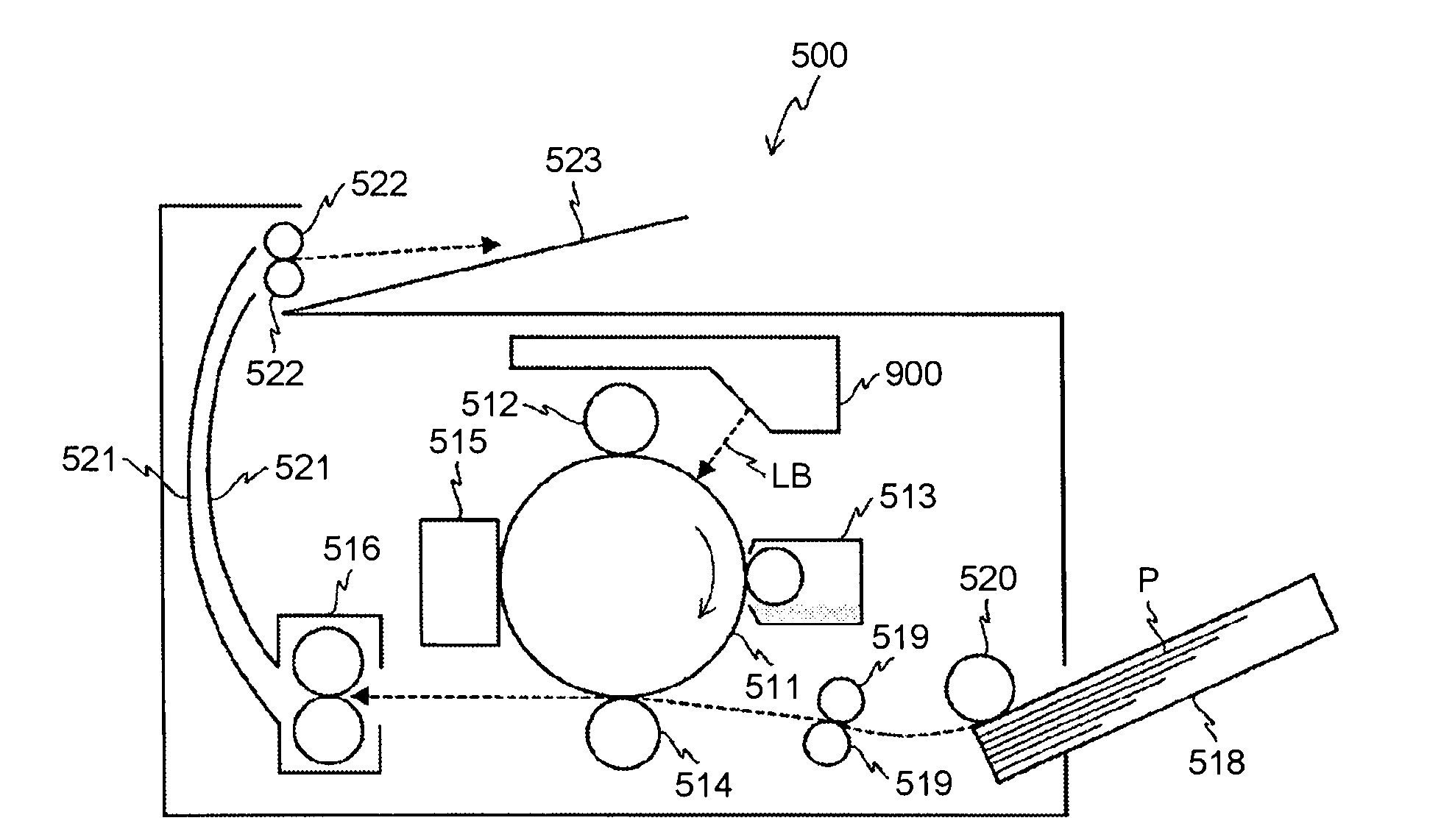
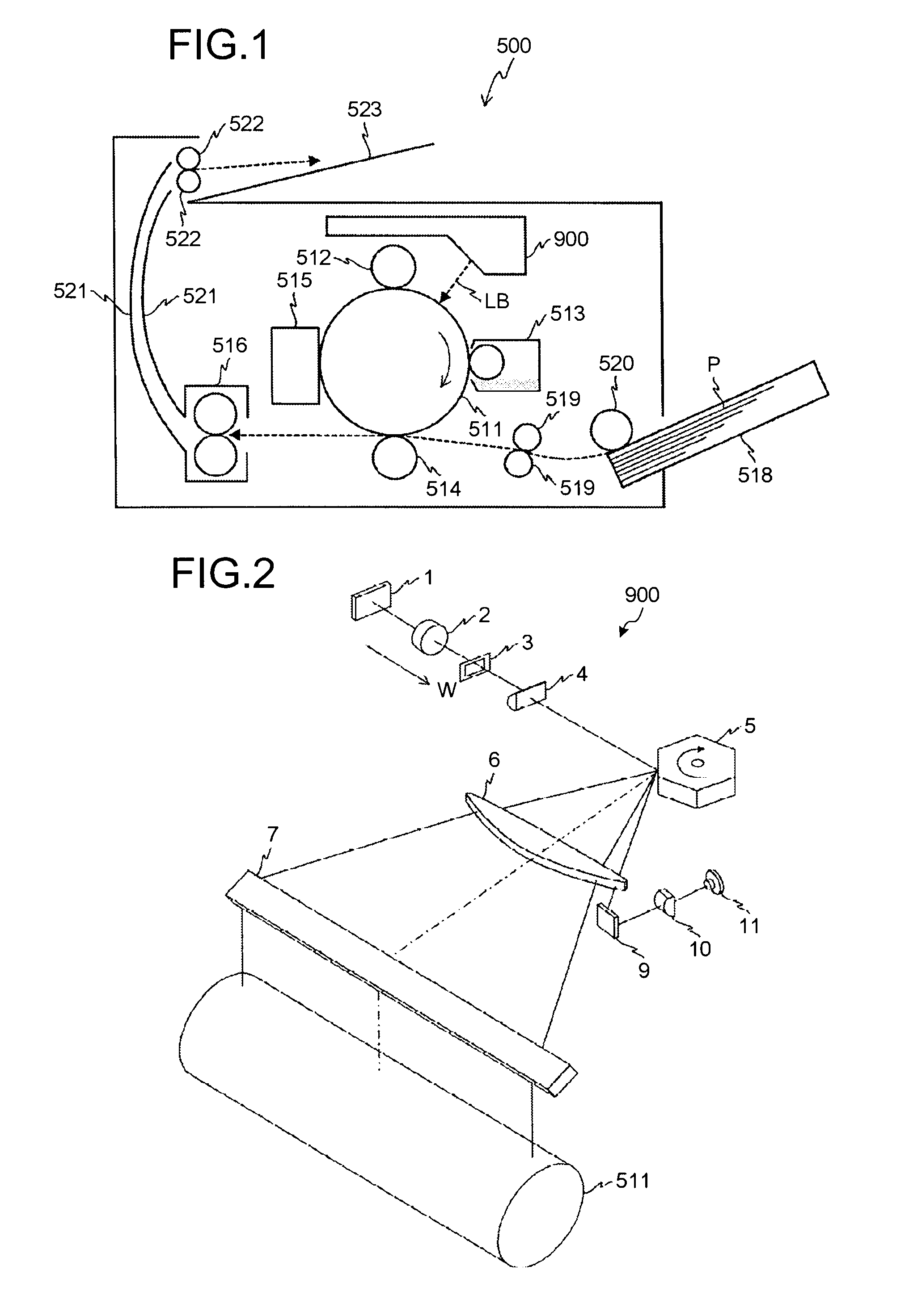
[0036]FIG. 1 is a schematic diagram of a laser printer 500 as an image forming apparatus according to an embodiment of the present invention.

[0037]The laser printer 500 includes a photosensitive drum 511, a charging roller 512, a developing unit 513, a transfer roller 514, a cleaning unit 515, a fixing unit 516, a paper feeding cassette 518, a pair of registration rollers 519, a paper feeding roller 520, a pair of discharging rollers 522, a catch tray 523, and an optical scanning device 900.

[0038]The photosensitive drum 511 is an image carrying member with a photoconductive, photosensitive outer surface that functions as a target surface for scanning.

[0039]The charging roller 512, the developing unit 513, the transfer roller 514, and the cleaning unit 515 are arranged in that order around t...


PUM


Abstract

An optical scanning device includes a light source, a pre-deflection optical system, a polygon mirror, and a scanning optical system. The pre-deflection optical system includes a coupling lens and a diffraction lens. A light output surface of the coupling lens is a phase shifting surface, while a light output surface of the diffraction lens is a diffractive surface. The absolute value of the focal length of the diffraction lens is longer than the absolute focal length of the coupling lens.

Description

CROSS-REFERENCE TO RELATED APPLICATIONS[0001]The present application claims priority to and incorporates by reference the entire contents of Japanese priority document 2007-219214 filed in Japan on Aug. 27, 2007.BACKGROUND OF THE INVENTION[0002]1. Field of the Invention[0003]The present invention relates to an optical scanning device arranged in an image forming apparatus.[0004]2. Description of the Related Art[0005]Conventionally, image forming apparatuses such as an optical printer, a digital copying machine, an optical plotter, and the like include an optical scanning device that uses a light beam to scan a target surface for scanning. Regarding such image forming apparatuses, the demand for low manufacturing cost and robustness against temperature fluctuation is on the increase in recent years.[0006]With the advances in high-precision processing technology, it is now possible to manufacture a robust optical scanning device having fewer components at low cost by using microstruct...

Claims


Application Information

Patent Timeline
IPC IPC(8): B41J2/47G02B26/08B41J27/00
CPCB41J2/471G02B27/0031G02B26/124G02B7/008
Inventor SAISHO, KENICHIROHIMAI, SHIGEAKI
Owner RICOH KK
Why Eureka
Try Eureka