Method of making head slider and resultant head slider

a slider and head technology, applied in the field of making a slider, can solve problems such as troublesome camfering process, and achieve the effect of high accuracy

Inactive Publication Date: 2009-02-26
TOSHIBA STORAGE DEVICE CORP
View PDF6 Cites 1 Cited by
  • Summary
  • Abstract
  • Description
  • Claims
  • Application Information

AI Technical Summary

Benefits of technology

[0009]The method employs a laser beam radiated to the corner of the back surface of the head slider. The material thus gets molten at least partly at the corner of the head slider. The molten material then gets cured or hardened. The corner of the head slider warps back. The corner of the medium-opposed surface is in this manner chamfered. The shape of the chamfer can clearly be observed. Such chamfering process can be repeated until a desired shape is obtained. In this manner, the head slider can readily be chamfered with a high accuracy.
[0010]The radiation conditions, such as duration of irradiation, energy of irradiation, the number of irradiation, and the like, of the laser beam can be specified for establishment of a desired shape. It is thus possible to chamfer the head slider with a high accuracy in accordance with the radiation conditions. Such radiation conditions enable establishment of the chamfer of a desired uniform shape on a plurality of head sliders.
[0014]When the slit is formed at the corner of the medium-opposed surface, the slit enables release of residual stress on the surface of the head slider. The corner of the medium-opposed surface is thus chamfered. The shape of the chamfer can clearly be observed. Such chamfering process can be repeated until a desired shape is obtained. In this manner, the head slider can readily be chamfered with a high accuracy.

Problems solved by technology

Chamfering process is troublesome.

Method used


Image

  • Method of making head slider and resultant head slider
  • Method of making head slider and resultant head slider
  • Method of making head slider and resultant head slider

Examples


Embodiment Construction

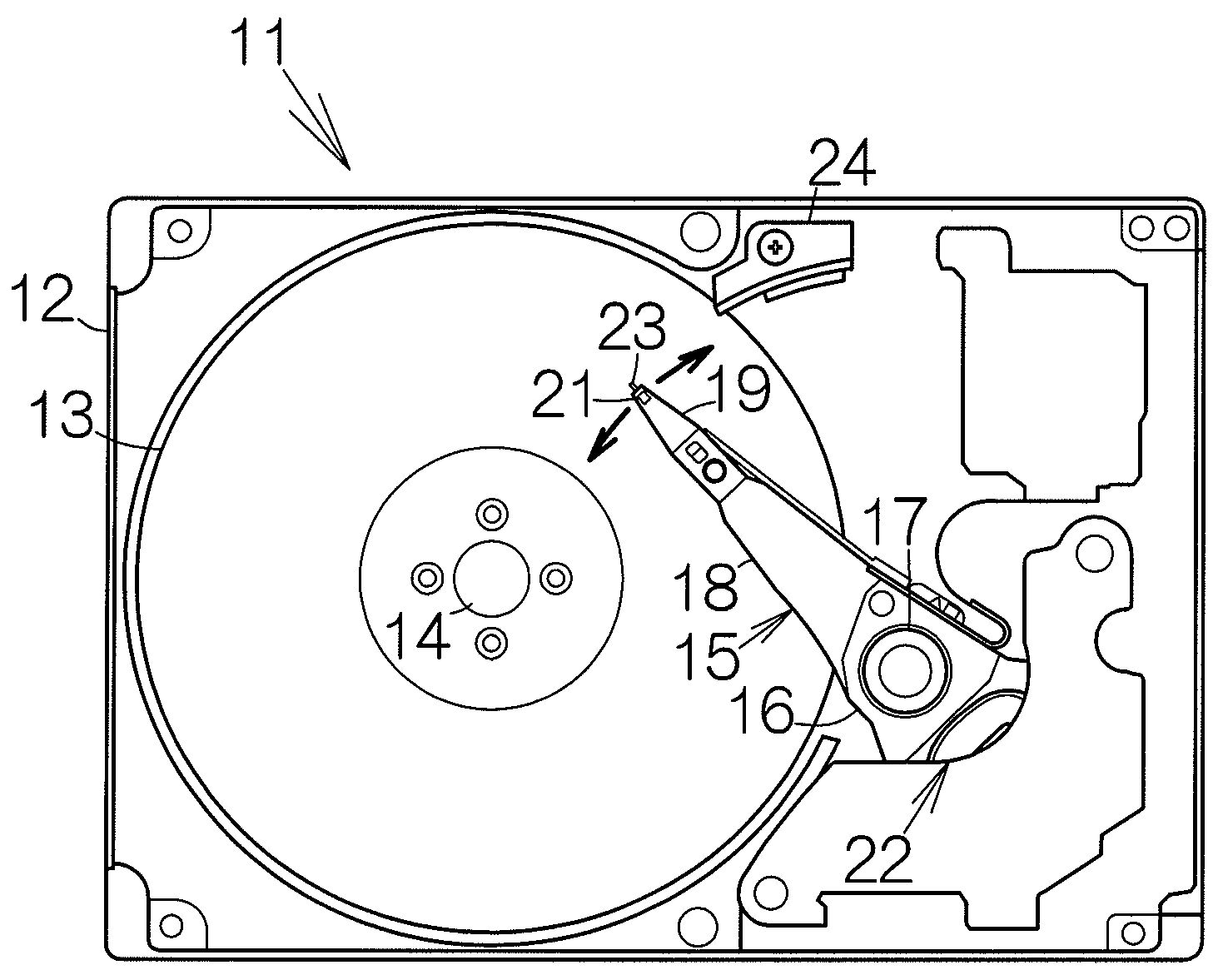
[0026]FIG. 1 schematically illustrates the structure of a hard disk drive, HDD, 11 as an example of a storage medium drive or storage apparatus. The hard disk drive 11 includes a box-shaped enclosure body 12 defining an inner space of a flat parallelepiped, for example. The enclosure body 12 may be made of a metallic material such as aluminum, for example. Molding process may be employed to form the enclosure body 12. An enclosure cover, not shown, is coupled to the enclosure body 12. The enclosure cover serves to close the opening of the inner space within the enclosure body 12. Pressing process may be employed to form the enclosure cover out of a plate material, for example.

[0027]At least one magnetic recording disk 13 as a storage medium is enclosed in the enclosure body 12. The magnetic recording disk or disks 13 are mounted on the driving shaft of a spindle motor 14. The spindle motor 14 drives the magnetic recording disk or disks 13 at a higher revolution speed such as 5,400 r...


PUM

PropertyMeasurementUnit
shrinkage stressaaaaaaaaaa
distanceaaaaaaaaaa
abrasiveaaaaaaaaaa

Abstract

A laser beam is radiated to the corner of the back surface of the head slider having the front surface defining a medium-opposed surface. This method employs a laser beam radiated to the corner of the back surface of the head slider. The material thus gets molten at least partly at the corner of the head slider. The molten material then gets cured or hardened. The corner of the head slider warps back. The corner of the medium-opposed surface is in this manner chamfered. The shape of the chamfer can clearly be observed. Such chamfering process can be repeated until a desired shape is obtained. In this manner, the head slider can readily be chamfered with a high accuracy.

Description

[0001]This application is a Continuation of International Application Serial No. PCT / JP2006 / 309473, filed May 11, 2006.BACKGROUND OF THE INVENTION[0002]1. Field of the Invention[0003]The present invention relates to a method of making a head slider incorporated in a hard disk drive, HDD, for example.[0004]2. Description of the Prior Art[0005]A head slider has a medium-opposed surface facing the surface of a hard disk, HD, at a distance, as disclosed in Japanese Patent Application Publication No. 2000-306226, for example. The corner of the medium-opposed surface of the head slider is chamfered. An inclined surface is thus formed. Even when the head slider collides against the surface of the hard disk, the inclined surface serves to reduce damages to the hard disk.[0006]The corner of the head slider is rubbed with a faceplate, for example. A slurry containing abrasive particles is dropped on the faceplate. The slurry covers over the inclined surface. The shape of the inclined surface ...

Claims


Application Information

Patent Timeline
Patent Type & Authority Applications(United States)
IPC IPC(8): G11B5/60A61N5/067
CPCG11B5/6005G11B5/102G11B5/3163G11B5/6082
Inventor HASHIMOTO, HIROKI
Owner TOSHIBA STORAGE DEVICE CORP
Why Eureka
Try Eureka