A chamfering jig for a flat block at the end of a shaft

A shaft end and chamfering technology, which is applied in the field of chamfering fixtures, can solve the problems of inability to guarantee the chamfering quality, time-consuming and labor-intensive, low production efficiency, etc., and achieves the effect of simple structure, convenient use and improved production efficiency.

Active Publication Date: 2017-10-31
JIHUA 3534 CLOTHING
View PDF2 Cites 0 Cited by
  • Summary
  • Abstract
  • Description
  • Claims
  • Application Information

AI Technical Summary

Problems solved by technology

[0002] The end of the shaft part is provided with a flat block, which is completed through the milling and flattening process. This flat block has four axial straight sides, two radial straight sides, and two arc sides. According to the design requirements Chamfer the four axial straight sides and two radial straight sides. In the prior art, there is no special chamfering fixture for this kind of flat block at the end of the shaft. Use a file for chamfering. The disadvantage of this operation method is that the operator needs to hold the processed shaft firmly, and the chamfering is easy to file to the arc surface of the shaft. The quality of the chamfering cannot be guaranteed, and it is labor-intensive and time-consuming. Low

Method used


Image

  • A chamfering jig for a flat block at the end of a shaft
  • A chamfering jig for a flat block at the end of a shaft
  • A chamfering jig for a flat block at the end of a shaft

Examples


Embodiment 1

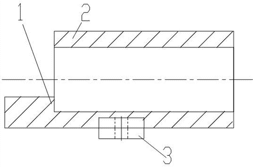
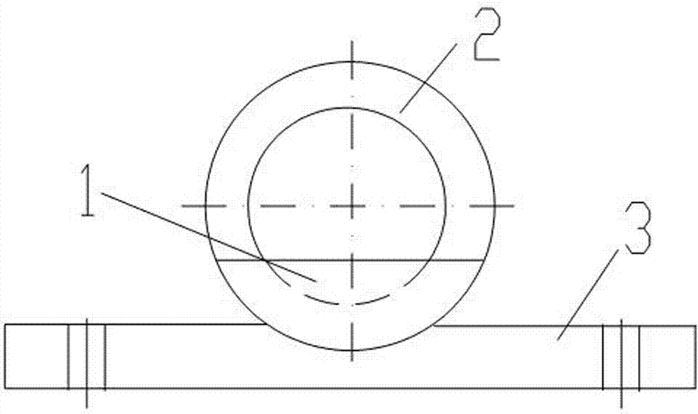
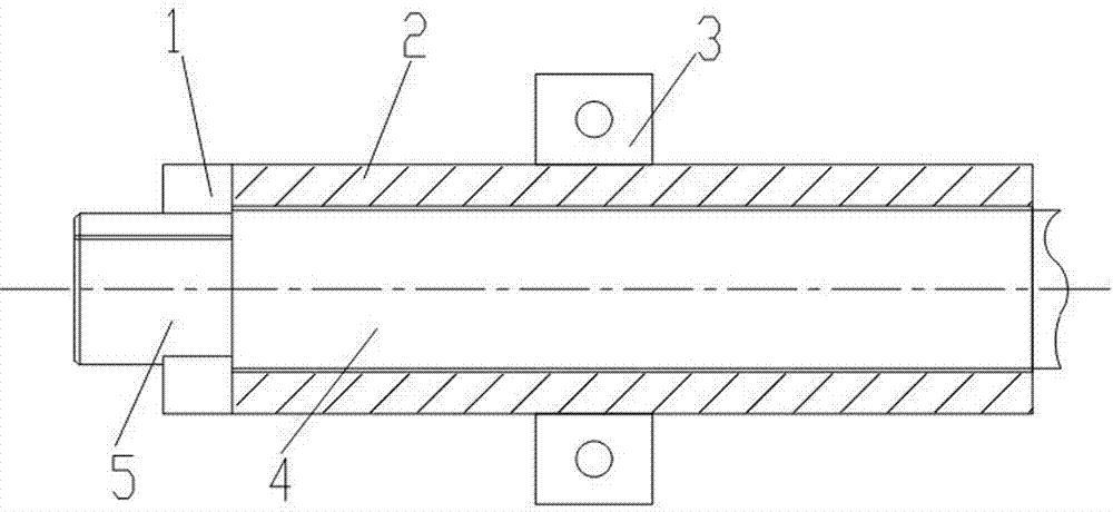
[0014] Embodiment 1: A chamfering jig for a flat block at the shaft end, including a shaft end sleeve 2, a blocking plate 1 and a fixing plate 3, the blocking plate 1 is a bow-shaped stop fixed on the inner wall of the left end of the shaft end sleeve 2 There is at least one arched baffle, and the fixed plate 3 is fixedly connected to both sides of the sleeve 2 . How to use: Insert the processed shaft 4 into the shaft end sleeve 2, block the shaft shoulder of the processed shaft 4 with the blocking plate 1, and make the shaft end flat block of the processed shaft 4 protrude. Since the processed shaft 4 is fixed as a whole, The operator holds the file to chamfer the flat block at the end of the shaft.

Embodiment 2

[0015] Embodiment 2: A chamfering jig for a flat block at the shaft end, including a shaft end sleeve 2, a blocking plate 1 and a fixing plate 3, the blocking plate 1 is a bow-shaped stop fixed on the inner wall of the left end of the shaft end sleeve 2 There is at least one arched baffle, and the fixed plate 3 is fixedly connected to both sides of the sleeve 2 . There are two blocking plates 1 and they are symmetrically fixed on the inner wall of the left end of the shaft end sleeve 2 . Using method is identical with embodiment 1.

Embodiment 3

[0016] Embodiment 3: A chamfering jig for a flat block at the shaft end, including a shaft end sleeve 2, a blocking plate 1 and a fixing plate 3, the blocking plate 1 is a bow-shaped stop fixed on the inner wall of the left end of the shaft end sleeve 2 There is at least one arched baffle, and the fixed plate 3 is fixedly connected to both sides of the sleeve 2 . There are two blocking plates 1 and they are symmetrically fixed on the inner wall of the left end of the shaft end sleeve 2 . It also includes a workbench 6 and a supporting sleeve 9. There are two shaft end sleeves 2 symmetrically arranged at both ends of the workbench 6. The shaft end sleeve 2 at the left end is fixedly connected with the workbench 6, and the shaft end sleeve 2 at the right end is fixedly connected to the workbench 6. The end sleeve 2 is slidingly connected with the worktable 6 through the bolt 8 and the chute 7 on the worktable 6, and the support sleeve 9 is fixed on the worktable 6 between the tw...


PUM


Abstract

The invention discloses a chamfering clamping apparatus of a shaft end flat block. The chamfering clamping apparatus comprises a shaft end sleeve, a plug board and a fixed board, wherein the plug board is an arch-shaped baffle plate fixed on the inner wall of the left end of the shaft end sleeve; at least one arch-shaped baffle plate is arranged; the fixed board is fixedly connected onto two sides of the sleeve. According to the invention, the plug board is the arch-shaped baffle plate and is penetrated into the shaft end sleeve by a processing shaft; the arch-shaped baffle plate blocks a shaft shoulder; the shaft end flat block stretches out of the shaft end sleeve, and is convenient to position and easy for chamfering processing. Two shaft end sleeves are adopted to mount and fix two ends of a processed shaft in a sleeving manner, the shaft end flat blocks at two ends stretch out respectively, the plug board blocks the shaft shoulder and supports the shaft end flat blocks to prevent rotation, and an operator can conveniently carry out chamfering operation; the chamfering clamping apparatus is simple in structure and convenient to use, can ensure the chamfering quality without damaging the shaft surface, can alleviate the labor intensity, and improves the production efficiency.

Description

technical field [0001] The invention relates to a chamfering jig, which is suitable for chamfering flat blocks at shaft ends. Background technique [0002] The end of the shaft part is provided with a flat block, which is completed through the milling and flattening process. This flat block has four axial straight sides, two radial straight sides, and two arc sides. According to the design requirements Chamfer the four axial straight sides and two radial straight sides. In the prior art, there is no special chamfering fixture for this kind of flat block at the end of the shaft. The disadvantage of this method of chamfering with a file is that the operator needs to hold the processed shaft firmly, and the chamfering is easy to file to the arc surface of the shaft, which cannot guarantee the quality of the chamfering, and it is labor-intensive and time-consuming. Low. Contents of the invention [0003] The technical problem to be solved by the present invention is to provi...

Claims


Application Information

Patent Timeline
Patent Type & Authority Patents(China)
IPC IPC(8): B23Q3/06
CPCB23Q3/064B23Q2703/10
Inventor 高子兴张仁俊刘志伟包卫强孙宏葵
Owner JIHUA 3534 CLOTHING
Why Eureka
Try Eureka