Chamfering clamping apparatus of shaft end flat block
A shaft end and chamfering technology, which is applied in the field of chamfering fixtures, can solve the problems of low production efficiency, inability to guarantee the quality of chamfering, labor-consuming, time-consuming and labor-intensive problems, and achieve the effects of simple structure, reduced labor intensity, and convenient use
- Summary
- Abstract
- Description
- Claims
- Application Information
AI Technical Summary
Problems solved by technology
Method used
Image
Examples
Embodiment 1
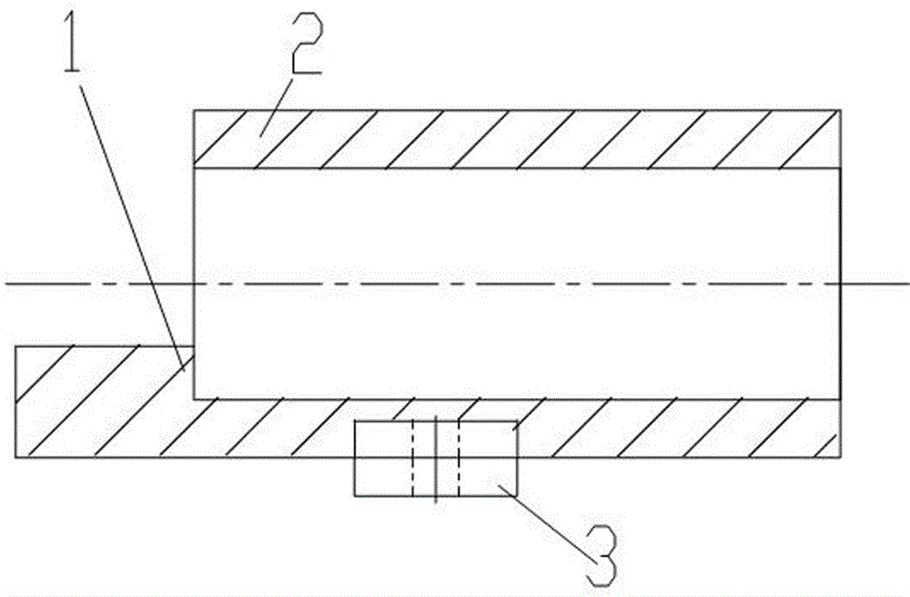
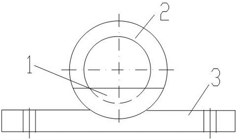
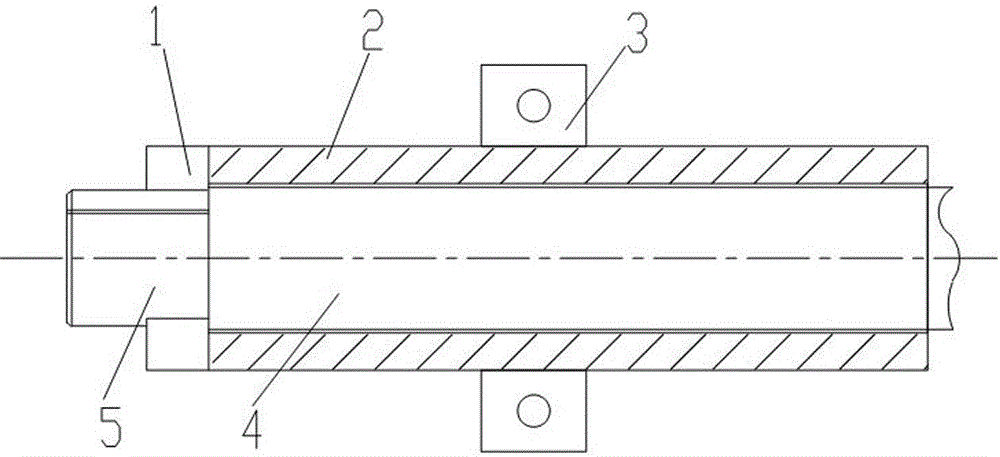
[0014] Embodiment 1: A chamfering jig for a flat block at the shaft end, including a shaft end sleeve 2, a blocking plate 1 and a fixing plate 3, the blocking plate 1 is a bow-shaped stop fixed on the inner wall of the left end of the shaft end sleeve 2 There is at least one arched baffle, and the fixed plate 3 is fixedly connected to both sides of the sleeve 2 . How to use: Insert the processed shaft 4 into the shaft end sleeve 2, block the shaft shoulder of the processed shaft 4 with the blocking plate 1, and make the shaft end flat block of the processed shaft 4 protrude. Since the processed shaft 4 is fixed as a whole, The operator holds the file to chamfer the flat block at the end of the shaft.
Embodiment 2
[0015] Embodiment 2: A chamfering jig for a flat block at the shaft end, including a shaft end sleeve 2, a blocking plate 1 and a fixing plate 3, the blocking plate 1 is a bow-shaped stop fixed on the inner wall of the left end of the shaft end sleeve 2 There is at least one arched baffle, and the fixed plate 3 is fixedly connected to both sides of the sleeve 2 . There are two blocking plates 1 and they are symmetrically fixed on the inner wall of the left end of the shaft end sleeve 2 . Using method is identical with embodiment 1.
Embodiment 3
[0016] Embodiment 3: A chamfering jig for a flat block at the shaft end, including a shaft end sleeve 2, a blocking plate 1 and a fixing plate 3, the blocking plate 1 is a bow-shaped stop fixed on the inner wall of the left end of the shaft end sleeve 2 There is at least one arched baffle, and the fixed plate 3 is fixedly connected to both sides of the sleeve 2 . There are two blocking plates 1 and they are symmetrically fixed on the inner wall of the left end of the shaft end sleeve 2 . It also includes a workbench 6 and a supporting sleeve 9. There are two shaft end sleeves 2 symmetrically arranged at both ends of the workbench 6. The shaft end sleeve 2 at the left end is fixedly connected with the workbench 6, and the shaft end sleeve 2 at the right end is fixedly connected to the workbench 6. The end sleeve 2 is slidingly connected with the worktable 6 through the bolt 8 and the chute 7 on the worktable 6, and the support sleeve 9 is fixed on the worktable 6 between the tw...
PUM
 Abstract
Description
Claims
Application Information
 - R&D
- Intellectual Property
- Life Sciences
- Materials
- Tech Scout
- Unparalleled Data Quality
- Higher Quality Content
- 60% Fewer Hallucinations
Browse by: Latest US Patents, China's latest patents, Technical Efficacy Thesaurus, Application Domain, Technology Topic, Popular Technical Reports.
© 2025 PatSnap. All rights reserved.Legal|Privacy policy|Modern Slavery Act Transparency Statement|Sitemap|About US| Contact US: help@patsnap.com


