A workpiece intelligent chamfering machine
A chamfering machine and intelligent technology, applied in the field of chamfering machines, can solve the problems of low positioning accuracy, manual cleaning of chamfering garbage, long maintenance time, etc., to facilitate positioning and maintenance, shorten maintenance time, and facilitate maintenance work. Effect
- Summary
- Abstract
- Description
- Claims
- Application Information
AI Technical Summary
Problems solved by technology
Method used
Image

Examples
Embodiment 1
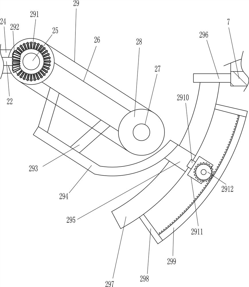
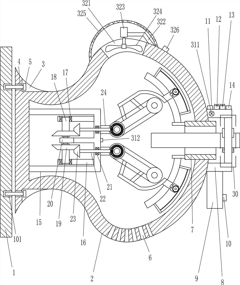
[0017] A workpiece intelligent chamfering machine, such as Figure 1-5As shown, it includes a mounting frame 2, a screw 5, a placement ring 7, a connection block 8, a control box 9, a power switch 10, a first switch 11, a first ship-type switch 12, a second ship-type switch 13, and a second switch 14 , N-shaped frame 15, extension rod 16, first bearing seat 17, first rotating rod 18, first bevel gear 19, first biaxial motor 20, second bearing seat 21, second rotating rod 22, second Bevel gear 23, mounting block 24, first rotating shaft 25, mounting rod 26, second rotating shaft 27, roller 28, abrasive belt 29, the 3rd bevel gear 291, the 4th bevel gear 292, connecting frame 293, curved bar 294, slider 295, connecting rod 296, curved slide rail 297, fixed rod 298, curved rack 299, extension block 2910, first reduction motor 2911, circular gear 2912 and centering device 30, body of wall 1 up and down There are first threaded holes 101 on both sides, a mounting frame 2 is provid...
Embodiment 2
[0019] A workpiece intelligent chamfering machine, such as Figure 1-5 As shown, it includes a mounting frame 2, a screw 5, a placement ring 7, a connection block 8, a control box 9, a power switch 10, a first switch 11, a first ship-type switch 12, a second ship-type switch 13, and a second switch 14 , N-shaped frame 15, extension rod 16, first bearing seat 17, first rotating rod 18, first bevel gear 19, first biaxial motor 20, second bearing seat 21, second rotating rod 22, second Bevel gear 23, mounting block 24, first rotating shaft 25, mounting rod 26, second rotating shaft 27, roller 28, abrasive belt 29, the 3rd bevel gear 291, the 4th bevel gear 292, connecting frame 293, curved bar 294, slider 295, connecting rod 296, curved slide rail 297, fixed rod 298, curved rack 299, extension block 2910, first reduction motor 2911, circular gear 2912 and centering device 30, body of wall 1 up and down There are first threaded holes 101 on both sides, a mounting frame 2 is provi...
Embodiment 3
[0022] A workpiece intelligent chamfering machine, such as Figure 1-5As shown, it includes a mounting frame 2, a screw 5, a placement ring 7, a connection block 8, a control box 9, a power switch 10, a first switch 11, a first ship-type switch 12, a second ship-type switch 13, and a second switch 14 , N-shaped frame 15, extension rod 16, first bearing seat 17, first rotating rod 18, first bevel gear 19, first biaxial motor 20, second bearing seat 21, second rotating rod 22, second Bevel gear 23, mounting block 24, first rotating shaft 25, mounting rod 26, second rotating shaft 27, roller 28, abrasive belt 29, the 3rd bevel gear 291, the 4th bevel gear 292, connecting frame 293, curved bar 294, slider 295, connecting rod 296, curved slide rail 297, fixed rod 298, curved rack 299, extension block 2910, first reduction motor 2911, circular gear 2912 and centering device 30, body of wall 1 up and down There are first threaded holes 101 on both sides, a mounting frame 2 is provid...
PUM
 Abstract
Description
Claims
Application Information
 - R&D
- Intellectual Property
- Life Sciences
- Materials
- Tech Scout
- Unparalleled Data Quality
- Higher Quality Content
- 60% Fewer Hallucinations
Browse by: Latest US Patents, China's latest patents, Technical Efficacy Thesaurus, Application Domain, Technology Topic, Popular Technical Reports.
© 2025 PatSnap. All rights reserved.Legal|Privacy policy|Modern Slavery Act Transparency Statement|Sitemap|About US| Contact US: help@patsnap.com