
Wave Soldering Bath

a soldering bath and wave technology, applied in the direction of non-electric welding apparatus, manufacturing tools, solventing apparatus, etc., can solve the problems of severe erosion using lead-free solder, no pb-sn soldering, and extreme danger, so as to achieve the effect of safe and long-term operation of solventing

Active Publication Date: 2009-02-26
SENJU METAL IND CO LTD
View PDF4 Cites 4 Cited by
  • Summary
  • Abstract
  • Description
  • Claims
  • Application Information

AI Technical Summary

Benefits of technology

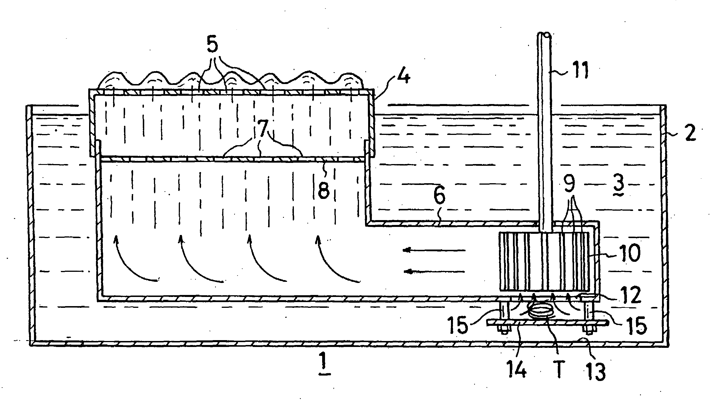
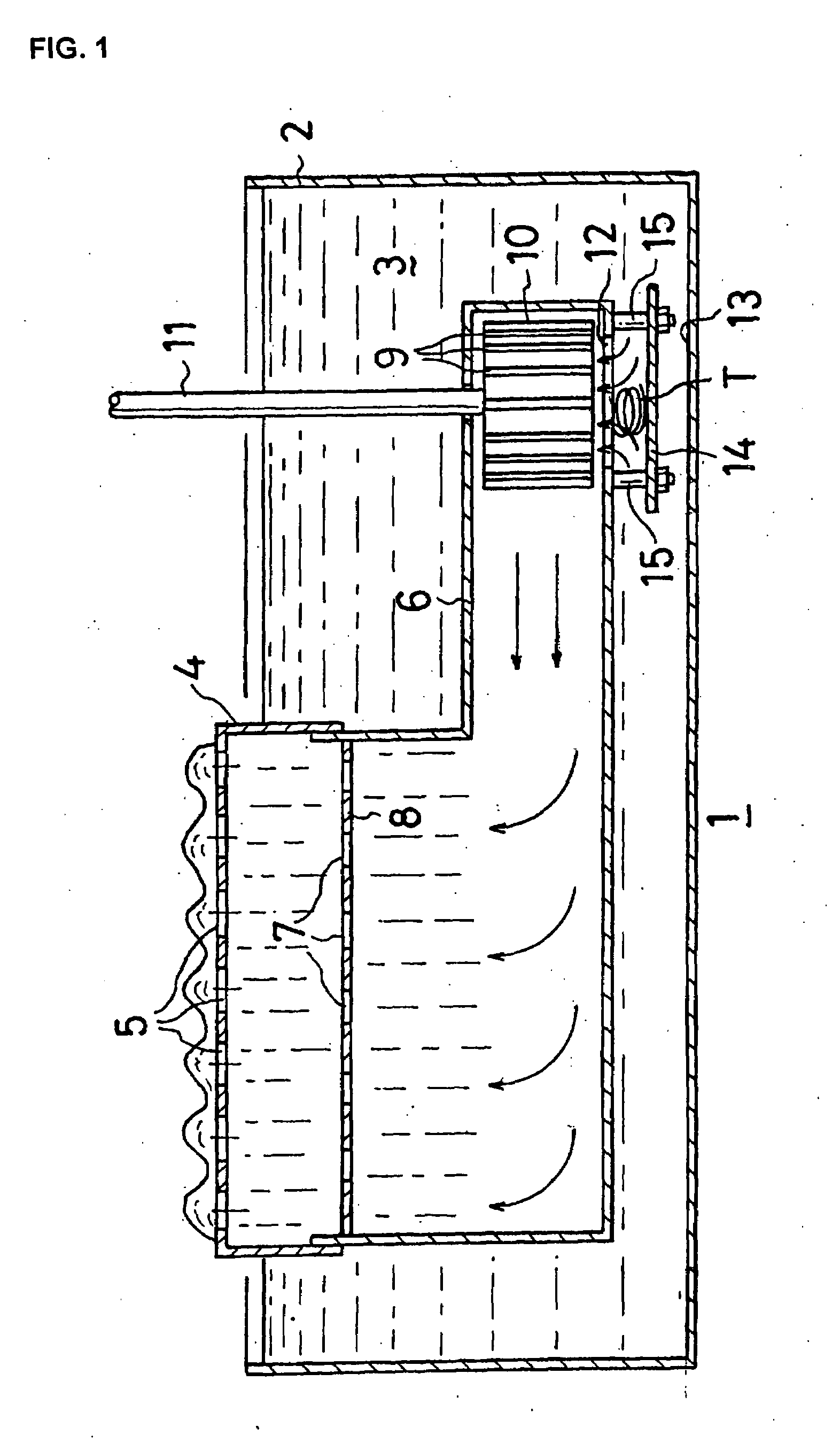
[0015]A wave soldering bath according to the present invention has a shielding member installed below an inlet beneath a pump. Therefore, even if a vortex develops above the shielding member, the vortex does not affect the bottom surface of the bath body, and as a result, the bottom surface of the bath body is not rubbed by a vortex of molten solder. Accordingly, in a wave soldering bath according to the present invention, the bottom surface of the bath body is not rubbed by molten solder and erosion does not develop therein, whereby the excellent effect that soldering operation can be safely carried out over long periods, which is not provided by a conventional wave soldering bath, can be obtained.

Problems solved by technology

Therefore, if a lead-free solder is used in a wave soldering bath, erosion which did not take place with a Pb-Sn solder ends up occurring.
As stated above, severe erosion using a lead-free solder takes place in a position of the bottom surface of a bath body below a duct where a pump is installed.
If the bottom surface of the bath body is eroded and a hole formed in it, all of the molten solder in the wave soldering bath will spill out and create an extremely dangerous situation.
In a wave soldering bath, the cause of the ready occurrence of erosion in the bottom surface of a bath body below the inlet of a duct is the formation of a vortex below the inlet of the duct.

Method used


Image

  • Wave Soldering Bath
  • Wave Soldering Bath
  • Wave Soldering Bath

Examples


Embodiment Construction

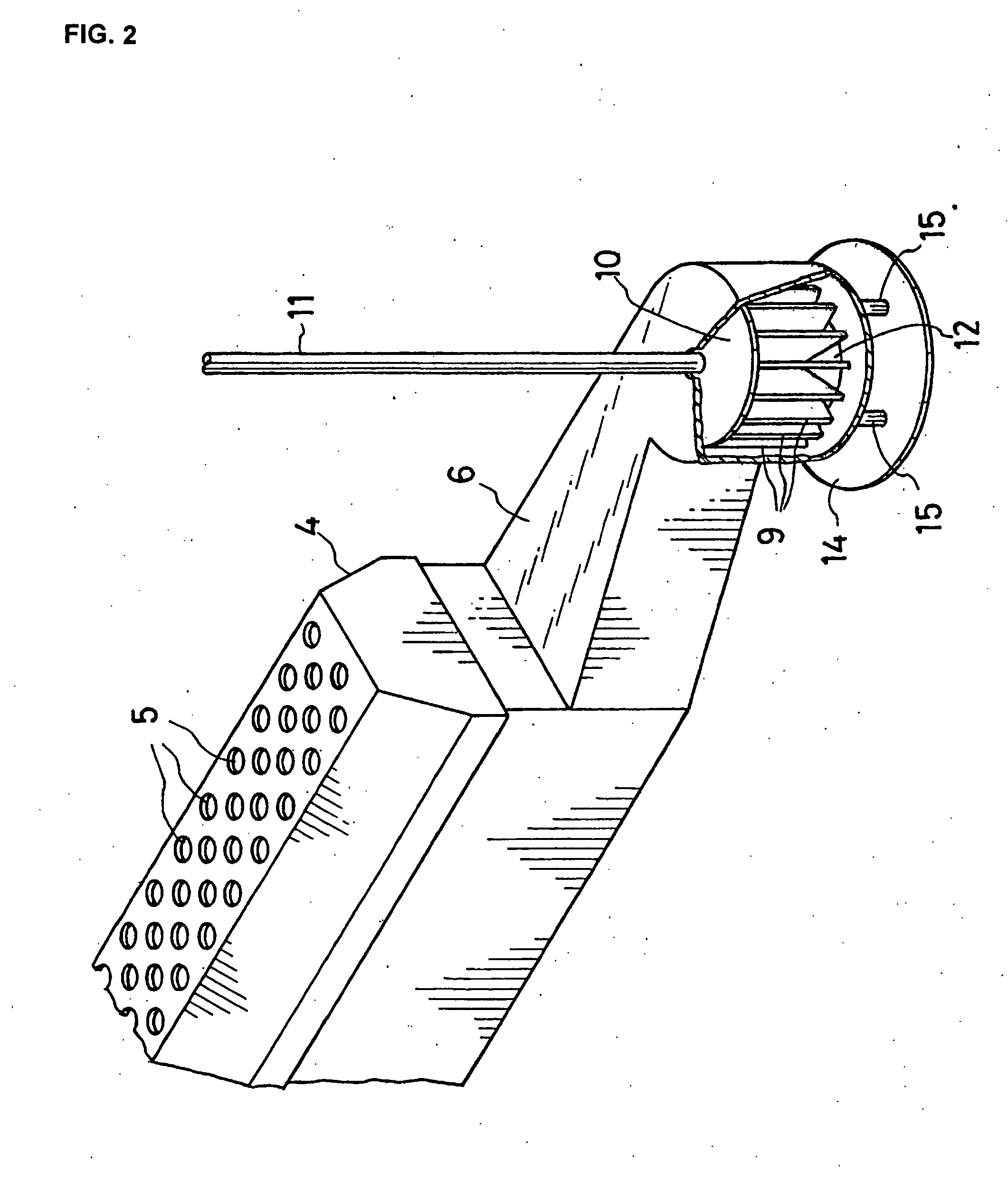
[0021]A wave soldering bath according to the present invention has a shielding (baffling) member installed between the inlet of a duct and the bottom surface of a bath body. The shielding member may be mounted on the duct, or it may be mounted on the bottom surface of the bath body.

[0022]A shielding member installed in a wave soldering bath according to the present invention is made of the same material as the bottom surface of the bath body, i.e., of stainless steel when it is permissible for the shielding member to undergo erosion. However, when the shielding member is desired to withstand erosion, although somewhat expensive, titanium or zirconium to which molten solder does not adhere at all is used. In order to prevent erosion when using stainless steel, a coating such as a fluorocarbon resin may be provided on the surface of the stainless steel, or the surface of the stainless steel may be subjected to nitriding treatment. A non-metallic material such as a ceramic or a heat-re...


PUM

PropertyMeasurementUnit
temperatureaaaaaaaaaa
melting pointaaaaaaaaaa

Abstract

In a conventional wave soldering bath, the bottom surface of a bath body in a position which is below the inlet of a duct underwent erosion by molten solder and had a hole formed therein, causing molten solder to be spilled out from the hole. The cause of erosion of the bottom surface of the bath body is a vortex (T) of molten solder formed below the duct inlet accompanying rotation of an impeller pump (10), and the vortex rubs the bottom surface of the bath body.In the present invention, a shielding member (14) is installed between the duct inlet (12) and the bottom surface (13) of the bath body such that the vortex is prevented from affecting the bottom surface.

Description

TECHNICAL FIELD[0001]This invention relates to a wave soldering bath for soldering of printed circuit boards with spouted molten solder.BACKGROUND ART[0002]Soldering of printed circuit boards which are incorporated into electric home appliances such as televisions and videos is carried out by flow soldering since such boards must be mass-produced inexpensively. Flow soldering can solder the entire surface of a printed circuit board in a single operation. Therefore, it is superior to other types of soldering with respect to mass productivity. An automatic soldering machine for carrying out soldering by flow soldering includes processing units such as a fluxer, a preheater, a wave soldering bath, and a cooler, and an endless conveyor runs above these processing units. When printed circuit boards are soldered in an automatic soldering machine, they successively undergo application of flux by the fluxer, preheating by the preheater, adhesion of solder in the wave soldering bath, and coo...

Claims


Application Information

Patent Timeline
Patent Type & Authority Applications(United States)
IPC IPC(8): B23K1/08
CPCB23K3/0653B23K1/085
Inventor ZEN, MITSUOICHIKAWA, HIROKAZU
Owner SENJU METAL IND CO LTD
Learn More