Solder repairing apparatus and method of repairing solder

a technology of solder repair and solder, which is applied in the direction of soldering apparatus, manufacturing tools,auxillary welding devices, etc., can solve the problem of accidental shift of the mounted component, and achieve the effect of preventing the recombination of the divided pieces

Inactive Publication Date: 2009-02-19
FUJITSU LTD
View PDF20 Cites 10 Cited by
  • Summary
  • Abstract
  • Description
  • Claims
  • Application Information

AI Technical Summary

Benefits of technology

[0007]It is accordingly an object of the present invention to provide a solder repairing apparatus and a method of repairing solder, enabling elimination of a short circuit in an electronic circuit in a relatively facilitated manner regardless of a reduction in the size of an electronic component.
[0008]According to a first aspect of the present invention, there is provided a solder repairing apparatus comprising: a stage designed to place the surface of at least a specific part of an object along a reference plane within a specific spot defined on the stage; a heating unit applying a thermal energy to the specific spot defined on the stage; and a dividing plate designed to move into the specific spot in a vertical attitude perpendicular to the reference plane, the dividing plate exhibiting a low solder wettability.
[0009]The solder repairing apparatus serves to locate solder at the specific spot on the stage. The solder melts in response to the application of the thermal energy. When the dividing plate in the vertical attitude enters the specific spot, the dividing plate gets into the solder. Since the dividing plate exhibits a low solder wettability, the dividing plate repels the solder. The solder is thus divided into two parts. The division of the solder reliably eliminates a short circuit in the electronic circuit.

Problems solved by technology

Hot air often causes the mounted component to accidentally shift from the predetermined mounting position.

Method used


Image

  • Solder repairing apparatus and method of repairing solder
  • Solder repairing apparatus and method of repairing solder
  • Solder repairing apparatus and method of repairing solder

Examples


Embodiment Construction

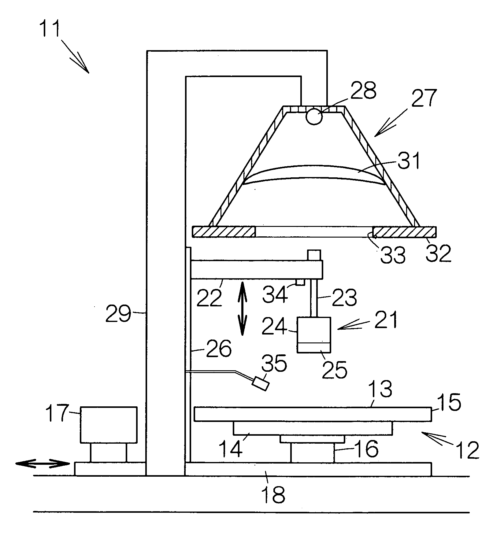
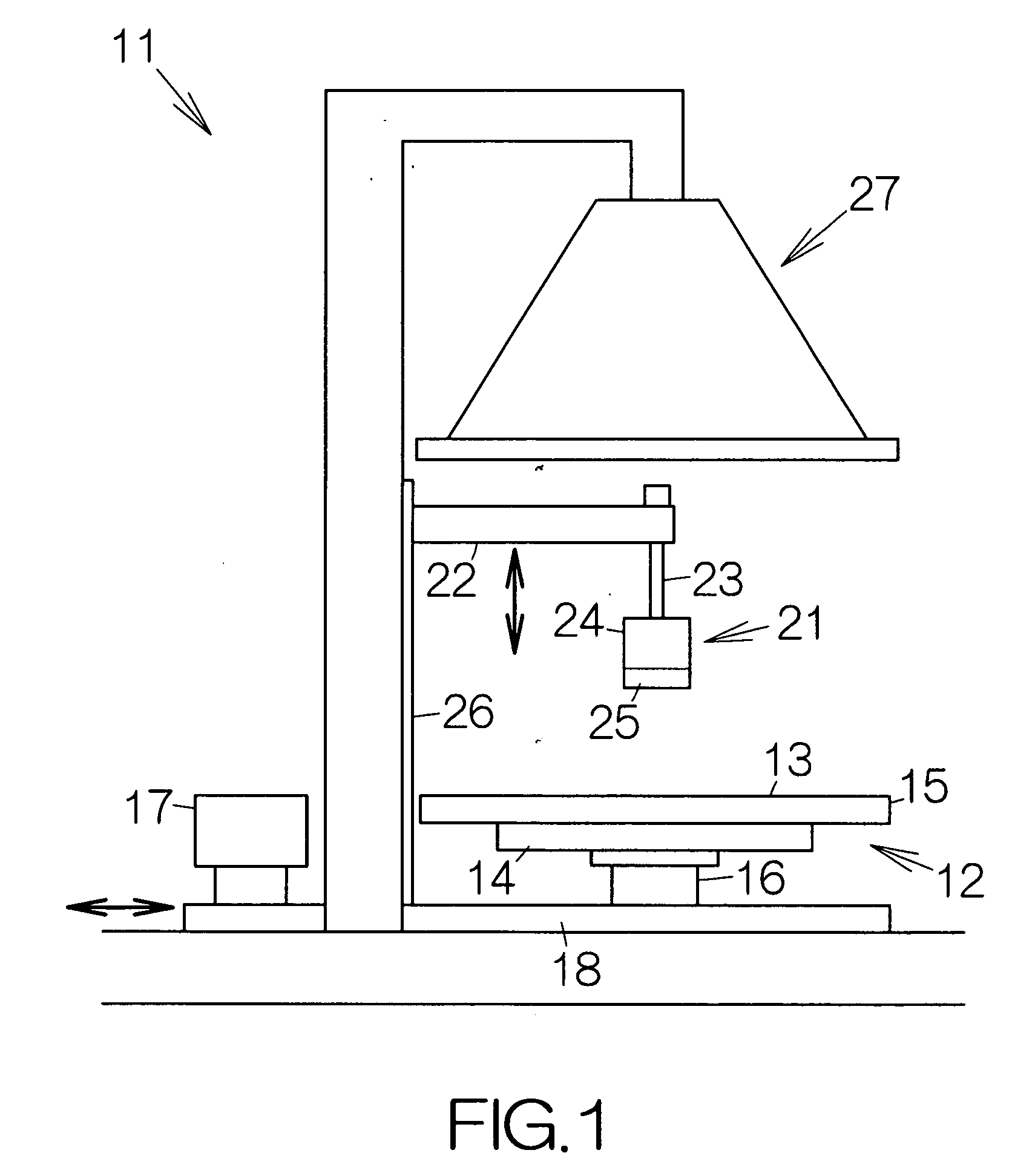
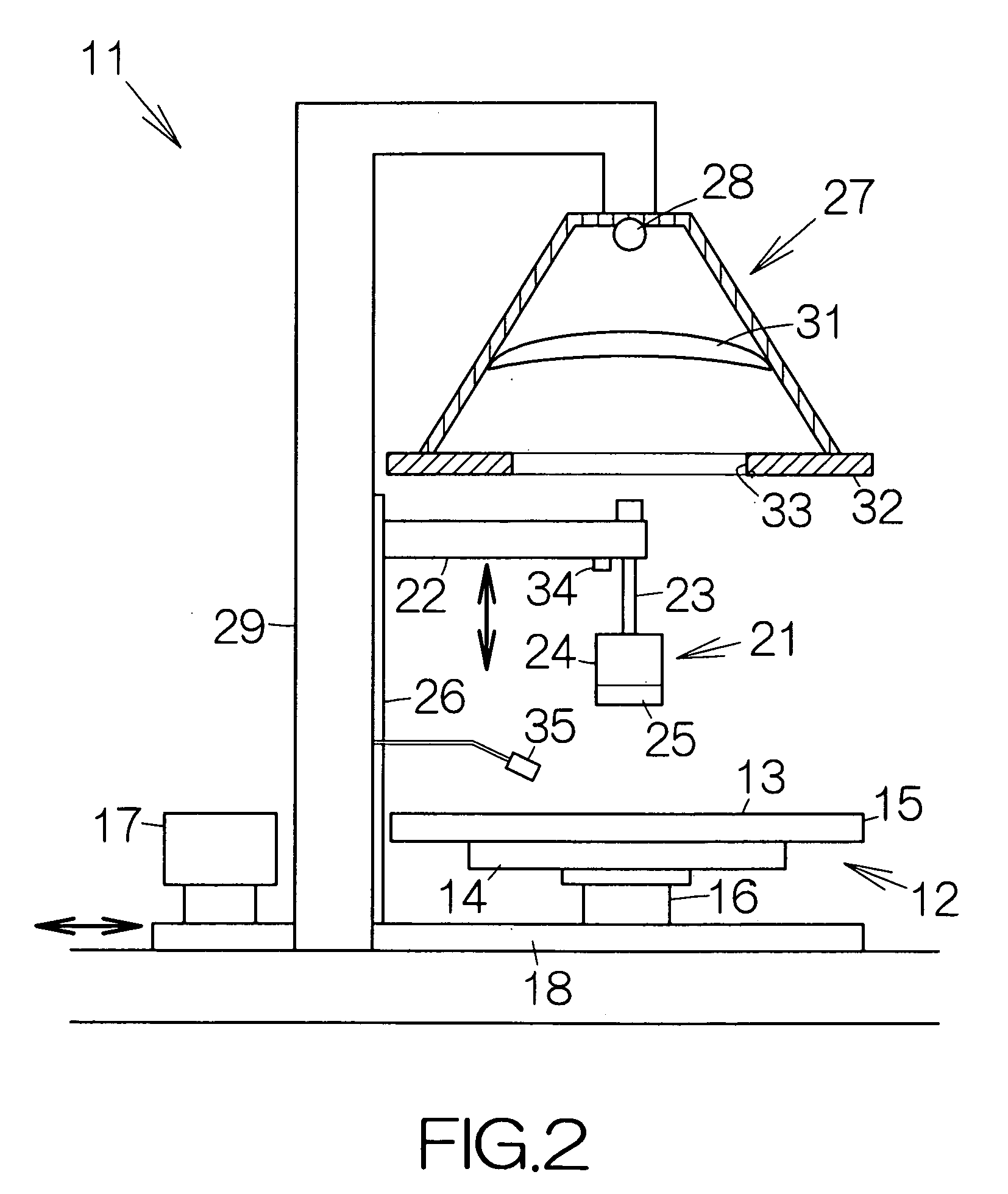
[0033]As shown in FIG. 1, a solder repairing apparatus includes a movable stage 12. The movable stage 12 defines a support surface 13 extending along a horizontal plane, namely a reference plane. The support surface 13 is allowed to move along the x-axis and the y-axis, perpendicular to each other within a horizontal plane. An X-axis stage 14 and a Y-axis stage 15 are incorporated in the movable stage 12 so as to realize the movement of the support surface 13. The X-axis stage 14 is driven to move in the direction of the x-axis within the horizontal plane. The Y-axis stage 15 is driven to move in the direction of the y-axis within the horizontal plane. A ball screw mechanism or a linear motor mechanism may be employed to realize the movement in the directions of the x-axis and the y-axis.

[0034]The solder repairing apparatus 11 includes a stage supporting mechanism 16. The stage supporting mechanism 16 is designed to support the movable stage 12 for relative rotation around a vertica...


PUM

PropertyMeasurementUnit
Fractionaaaaaaaaaa
Energyaaaaaaaaaa
Wettabilityaaaaaaaaaa

Abstract

A solder repairing apparatus includes a stage designed to place the surface of at least a specific part of an object along a reference plane within a specific spot defined on the stage. A heating unit applies a thermal energy to the specific spot. A dividing plate is designed to move into the specific spot in a vertical attitude perpendicular to the reference plane. The dividing plate exhibits a low solder wettability. The solder melts in response to the application of the thermal energy. When the dividing plate in the vertical attitude enters the specific spot, the dividing plate gets into the solder. Since the dividing plate exhibits a low solder wettability, the dividing plate repels the solder. The solder is divided into two parts. The division of the solder reliably eliminates a short circuit in the electronic circuit.

Description

BACKGROUND OF THE INVENTION[0001]1. Field of the Invention[0002]The present invention relates to a so-called solder repairing apparatus and a method of repairing solder.[0003]2. Description of the Prior Art[0004]Two or more electronic components are mounted on a printed wiring board in a printed circuit board unit. Solder is employed to mount the electronic components on the printed wiring board. The solder often happens to bridge two or more electrode pads on the printed wiring board. A short circuit is established in an electronic circuit on the printed wiring board. Such a printed circuit board unit cannot be shipped out of a factory.[0005]It is required to eliminate such a short circuit in the electronic circuit of the printed circuit board unit. The corresponding electronic component is removed from the printed wiring board so as to eliminate the short circuit. A new electronic component is then mounted on the printed wiring board. Repair of the solder thus causes the replaceme...

Claims


Application Information

Patent Timeline
IPC IPC(8): B23K31/02B23K37/00B23Q15/00
CPCB23K1/018B23K3/029H05K3/225H05K3/3442H05K3/3494H05K2203/175H05K2203/0195H05K2203/0445H05K2203/107H05K2203/1105H05K2201/2081
Inventor YAMAMOTO, KEIICHIOKADA, TORU
Owner FUJITSU LTD
Why Eureka
Try Eureka