
Descending device and method of use

Inactive Publication Date: 2009-02-19
RIT SAFETY SOLUTIONS
View PDF10 Cites 8 Cited by
  • Summary
  • Abstract
  • Description
  • Claims
  • Application Information

AI Technical Summary

Benefits of technology

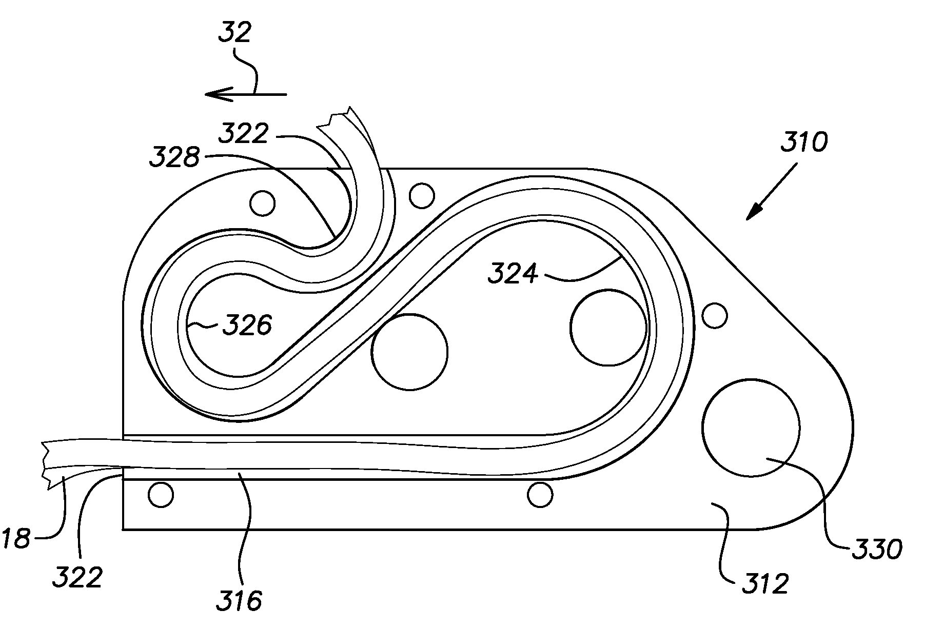
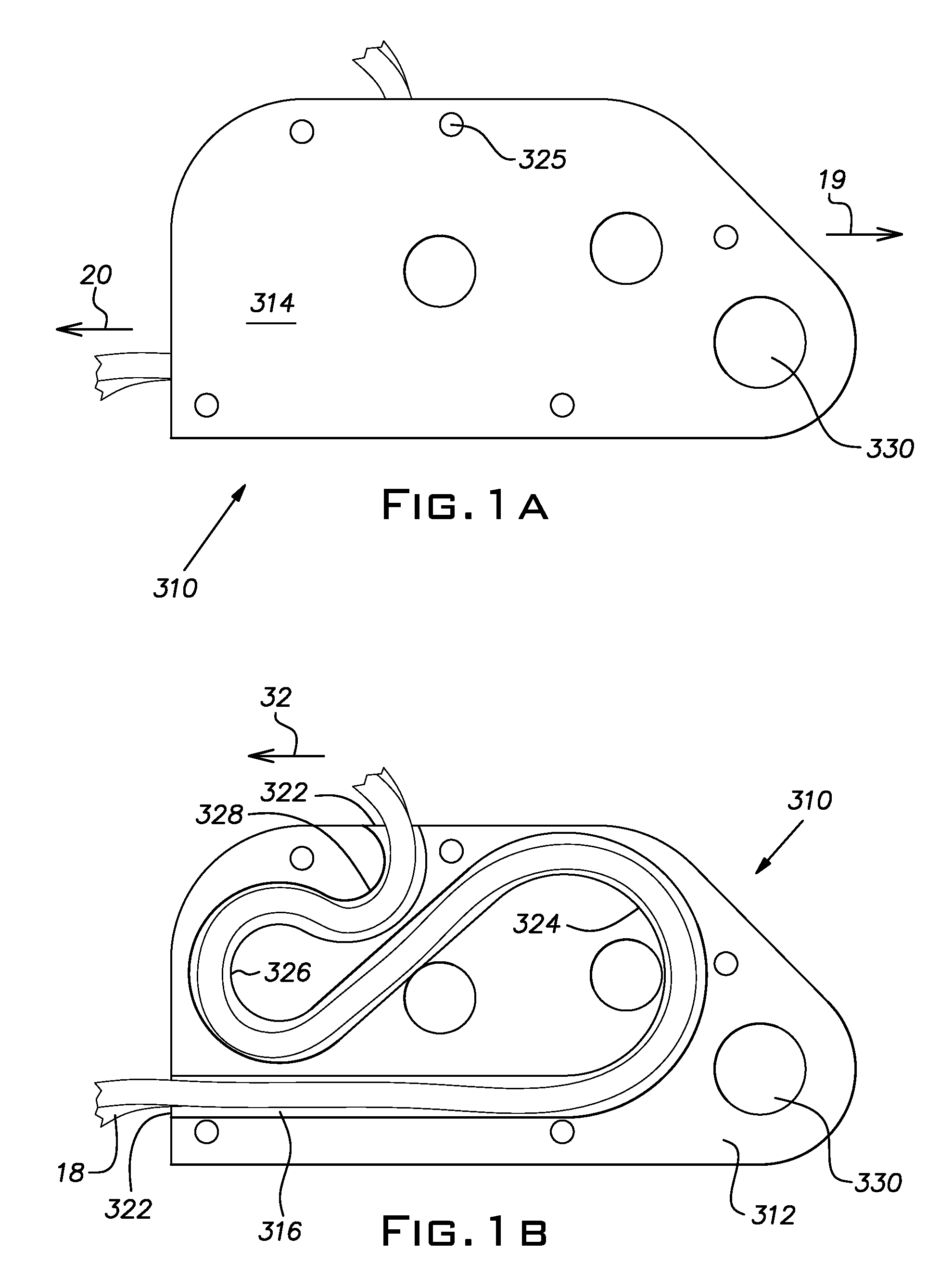
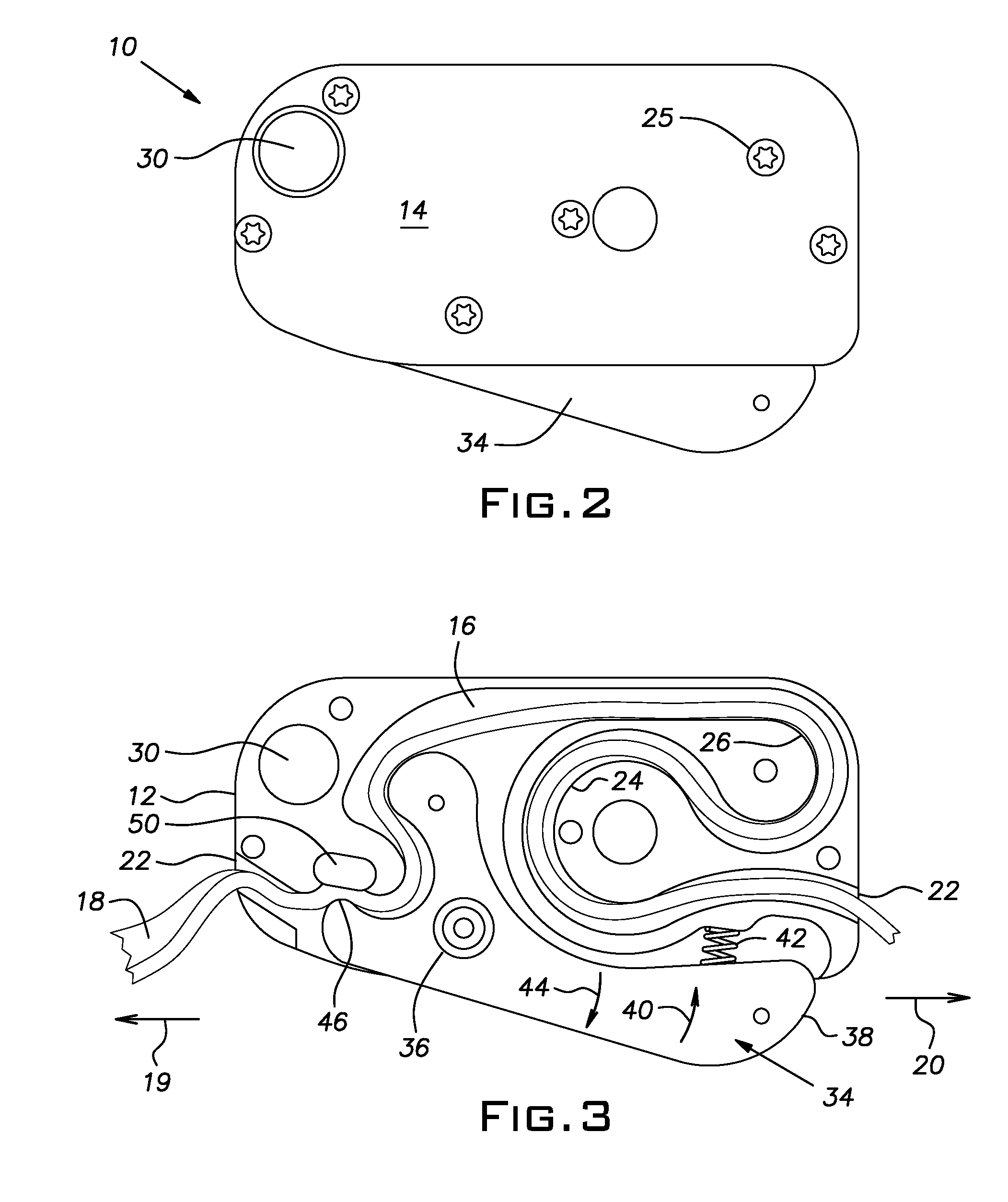
[0011]According to another aspect, the present invention provides a descending device to be used by a user to control a rate of descent. The descending device according to the current aspect includes a housing comprising a channel for receiving a tether along which the descending device is to travel during a descent, and a cover for concealing at least a portion of the channel to minimize introduction of foreign bodies into the serpentine pathway. A descent control lever to be manually actuated between a plurality of positions by the user is provided to allow the user to selectively control the rate of descent. Said plurality of positions includes a first position actuated by strongly squeezing the lever, said first position stopping the rate of descent; a second position actuated by loosely or not squeezing the lever, said second position also stopping the rate of descent; and a third position between said first and said second position, said third position controlling the rate of descent determined by an amount of squeezing of the lever.
[0012]According to another aspect, the present invention provides a method of using a descending device as disclosed and claimed herein for descending down a building. The method includes the steps of providing the tether, providing the descending device with the tether wound therethrough, connecting one end of the tether to a fixed structure, connecting another end of the tether to a user, and the user rappelling down a side of a building or the structure by controlling the rate of descent by the user variably squeezing the lever.

Problems solved by technology

The use of such tight bends in descending devices to create enough friction for a controlled descent is not recommended for all types of ropes or webbing, however.
Thus, descending devices including very sharp bends or kinks to create enough friction to slow a rate of feed of the rope, web, etc. through the descending devices may not be convenient for use with ropes, webbings, etc., made from such modern fibers.
Conventional descending devices also lack features that can help control the rate of descent during panic situations (where, for example, a user might grip a device too hard), or where the user may be disabled (and thus not be able to grip the device at all).
Furthermore, prior art descending devices tend to require two hands to operate, typically one to operate the device, and the second to hold onto the rope, web, etc., especially during horizontal travel, such as toward a window, as the user tries to play out the rope, web, etc.
The requirement of using two hands means that no hands are available for other important tasks, such as rescuing another person or carrying important equipment, for example
In addition, typical descending devices on the market for personal egress are open units, meaning the rope or webbing is substantially exposed, which can allow debris or unwanted elements to enter the device and affect its performance.
And conventional descending devices are specific to left-handed and right-handed people, requiring a separate descending device for each, increasing equipment costs for rescue crews.

Method used


Image

  • Descending device and method of use
  • Descending device and method of use
  • Descending device and method of use

Examples


Embodiment Construction

[0022]Certain terminology is used herein for convenience only and is not to be taken as a limitation on the present invention. Relative language used herein is best understood with reference to the drawings, in which like numerals are used to identify like or similar items. Further, in the drawings, certain features may be shown in somewhat schematic form.

[0023]It is also to be noted that the phrase “at least one of”, if used herein, followed by a plurality of members herein means one of the members, or a combination of more than one of the members. For example, the phrase “at least one of a first widget and a second widget” means in the present application: the first widget, the second widget, or the first widget and the second widget. Likewise, “at least one of a first widget, a second widget and a third widget” means in the present application: the first widget, the second widget, the third widget, the first widget and the second widget, the first widget and the third widget, the...


PUM


Abstract

Provided is a descending device and method for controlling a rate of descent. The descending device includes a housing comprising a channel for receiving a tether along which the descending device is to travel during a descent. A cover conceals at least a portion of the serpentine pathway to minimize introduction of foreign bodies into the serpentine pathway. A first arcuate surface defines at least a portion of the serpentine pathway and a second arcuate surface defines at least another portion of the serpentine pathway. Each of the first and second arcuate surfaces includes a different radius of curvature. The descending device also includes at least one of a third arcuate surface adjacent to an entrance to the serpentine pathway and having a third radius of curvature that is shorter than both the first radius of curvature and the second radius of curvature, and a descent control lever to be manually actuated between a plurality of positions by the user to selectively control the rate of descent.

Description

CROSS-REFERENCE TO RELATED APPLICATIONS[0001]This application claims the benefit of U.S. Provisional Application No. 60 / 956,016, filed Aug. 15, 2007, the entirety of which is incorporated herein by reference.TECHNICAL FIELD[0002]This application relates generally to a device to control a rate of descent for an egress system and a method of using same.BACKGROUND OF THE INVENTION[0003]Fire service, rock climbing, high angle rescue and technical rescue teams have utilized descending devices to create friction against a rope (or more recently a webbing) to allow for a controlled vertical descent. More recently, uses have been developed for personal emergency egress and self rescue from various heights. Emergencies can occur in almost any industry working from heights that would warrant self rescue or emergency escape. Ropes or webbing and their corresponding descending devices have grown smaller in size and shape to accommodate for personal use. One of the smallest diameter ropes or web...

Claims


Application Information

Patent Timeline
IPC IPC(8): A62B1/14A62B1/06A62B1/20
CPCA62B1/14
Inventor JORDAN, OMAR P.
Owner RIT SAFETY SOLUTIONS
Learn More