
Preform for composite material and process for producing the same

a technology of composite materials and preforms, which is applied in the direction of thin material processing, ceramic layered products, transportation and packaging, etc., can solve the problems of deformation of preforms for composite materials, fractures or cracks in molded metal composite materials, and metal composite materials that do not sufficiently exhibit mechanical characteristics, etc., to achieve superior air permeability, high strength, and the effect of high strength

Inactive Publication Date: 2009-02-05
CENTRAL MOTOR WHEEL CO LTD +2
View PDF1 Cites 8 Cited by
  • Summary
  • Abstract
  • Description
  • Claims
  • Application Information

AI Technical Summary

Benefits of technology

[0008]In general, there is a tendency that the strength of a preform for a composite material is improved whilst the air permeability is reduced with an increase of the content of ceramic fibers or ceramic particles in the preform. Similarly, the air permeability is improved whilst the strength is reduced with a decrease of the content. Thus, in the preform for a composite material, it is not easy to improve both the strength and air permeability at the same time.
[0045]An aspect of the present invention provides a process in which aluminum borate particles having a particle size of 10 μm or less are mixed as the ceramic particles to form an aqueous mixture liquid, the aluminum borate particles react with the silica sol and with the calcium monoxide produced by decomposition of the calcium carbonate in the sintering step to form a calcium-boron-silicon sinter. A preform for a composite material in which the ceramic fibers or / and the ceramic particles are bound to each other by the calcium-boron-silicon sinter shows higher strength and excellent permeability as compared with the preform having the above-described conventional structure.

Problems solved by technology

If, on the other hand, the preform for a composite material is not sufficiently impregnated with the melt, relatively large cavities (unimpregnated portions) will be formed in the metal composite so that the metal composite material will fail to sufficiently exhibit the mechanical characteristics.
Thus, when the above-described preform for a composite material having the conventional structure is impregnated with a melt of a light metal, the melt cannot sufficiently flow thereinto, thereby forming above-mentioned cavities in the metal composite material.
Further, when the impregnation of the melt of a light metal is carried out by a high-speed die casting method, there are problems that the preform for a composite material is deformed and fractures or cracks are formed in the molded metal composite material.
The deformation and formation of cracks are considered to be caused by lack in strength of the preform for a composite material.
Thus, the conventional structure in which binding between the reinforcing material bodies is attained by the inorganic binder is ill-suited for a high-speed die casting method.
Thus, in the preform for a composite material, it is not easy to improve both the strength and air permeability at the same time.

Method used


Image

  • Preform for composite material and process for producing the same
  • Preform for composite material and process for producing the same
  • Preform for composite material and process for producing the same

Examples


example 1

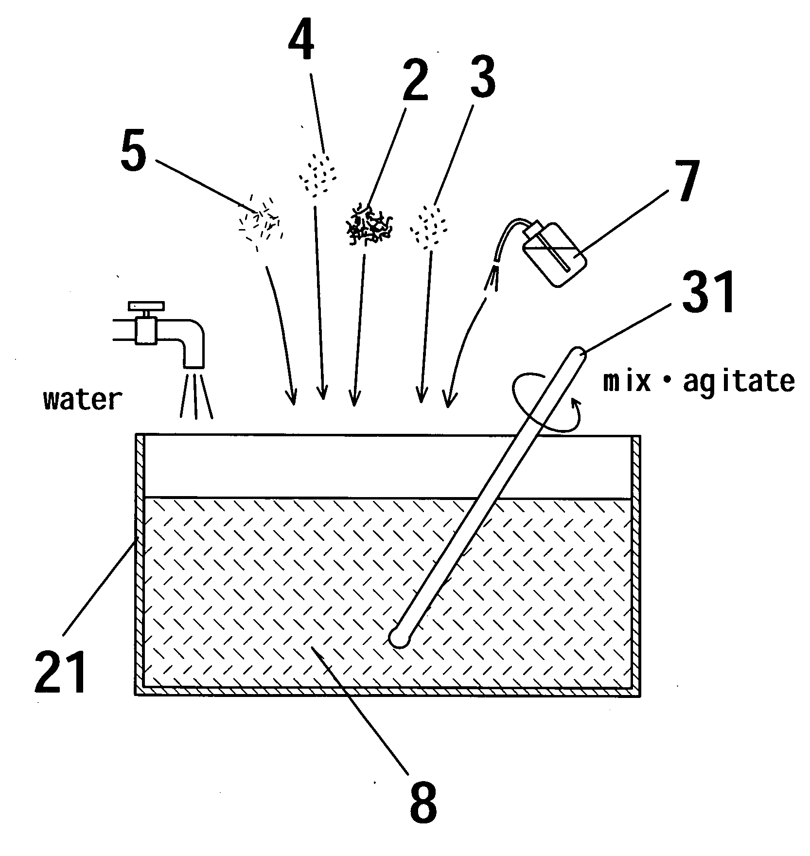
[0062]In the above-described mixing step (FIG. 1A), the following materials (i) to (v) are added to water in a vessel 21.

(i) Alumina short fibers 2 (average fiber diameter: 5 μm, average bulk ratio: 20 cc / 5 gf)

(ii) Aluminum borate particles 3 (9Al2O3.2B2O3, average particle diameter: 30 μm)

(iii) Calcium carbonate particles 4 (CaCO3, average particle diameter: 0.3 μm)

(iv) Graphite particles 5 (average particle diameter: 20 μm)

(v) Silica sol 7 (SiO2, aqueous colloidal solution having a concentration of about 40%)

[0063]The average fiber diameter, average bulk ratio and average particle diameter are mean values of the fiber diameter, bulk ratio and particle diameter, respectively, and there are variations. The alumina short fibers 2 are ceramic fibers according to the present invention. The aluminum borate particles 3 and graphite particles 5 are ceramic particles according to the present invention. These ceramic fibers and ceramic particles are so called reinforcing materials.

[0064]Usi...

example 2

[0078]In Example 2, the following materials (i) to (v) are added to water in a vessel 21 to perform the mixing step (FIG. 1A) of a preform production process.

(i) Alumina short fibers 2 (average fiber diameter: 5 m, average bulk ratio: 20 cc / 5 gf)

(ii) Aluminum borate particles 3 (9Al2O3.2B2O3, average particle diameter: 3 m)

(iii) Calcium carbonate particles 4 (CaCO3, average particle diameter: 0.3 μm)

(iv) Graphite particles 5 (average particle diameter: 20 μm)

(v) Silica sol 7 (SiO2, aqueous colloidal solution having a concentration of about 40%)

[0079]The materials are the same as those in Example 1 except that the aluminum borate particles have an average particle diameter of 3 μm. The mixing amount of the aluminum borate particles is the same as that of the aluminum borate particles 3 in Example 1. In the following description, steps and constitution similar to those in Example 1 are omitted and similar reference numerals are affixed to the same components.

[0080]An aqueous mixture l...


PUM

PropertyMeasurementUnit
particle sizeaaaaaaaaaa

Abstract

A preform for a composite material which has high strength and excellent air permeability and hence is applicable to a high-speed die casting method and which is capable of forming a metal composite material having excellent mechanical properties by a high-speed die casting method. Also provided is a process for producing such a preform. Ceramic fibers or / and ceramic particles are mixed with a silica sol and calcium carbonate and sintered at a predetermined temperature to form a calcium / silicon sinter obtained from the silica sol and calcium carbonate. The calcium / silicon sinter coats the ceramic fibers or / and ceramic particles so that a preform having the fibers or / and the particles bound to each other by the calcium / silicon sinter is obtained. The preform for a composite material has high strength and excellent air permeability and is applicable to the high-speed die casting method capable of attaining high productivity.

Description

CROSS REFERENCE TO PRIOR RELATED APPLICATIONS[0001]This is a U.S. National Phase application under 35 U.S.C. §371 of International Application No. PCT / JP2007 / 051663, filed on Feb. 1, 2007, and claims the benefit of Japanese Patent Application No. 2006-028698, filed on Feb. 6, 2006. Both applications are incorporated herein by reference. The International Application was published in Japanese on Aug. 16, 2007 as WO 2007 / 091471 A1 under PCT Article 221(2).FIELD[0002]The present invention is directed to a preform for forming a composite material used for forming a metal composite material by being composited with a light metal such as an aluminum alloy, and to a process for producing the same.BACKGROUND[0003]In order to improve fuel efficiency and driving stability in, for example, automobiles, there is a tendency to increasingly use parts made of a light metal such as aluminum which is excellent in light weight, high durability, low thermal expansion, etc. In particular, a metal compo...

Claims


Application Information

Patent Timeline
Patent Type & Authority Applications(United States)
IPC IPC(8): B32B18/00C04B35/14C04B35/44
CPCB22D17/12Y10T428/252C04B28/24C22C47/02C22C47/12C22C49/04B22D19/14C04B2235/80C04B2235/5445C04B2235/5436C04B2235/5264C04B35/01C04B35/013C04B35/64C04B35/803C04B2235/3208C04B2235/3217C04B2235/3409C04B2235/3418C04B2235/3454C04B2235/36C04B2235/425C04B2235/442C04B2235/5224C04B14/28C04B14/30C04B14/46C04B40/0268C04B35/80
Inventor FUJITA, MAKOTOKUMAGAI, KUNIOHASHIMOTO, MASAOKIHASHIMOTO, KAZUKOUEBAYASHI, HIDENORIKAWAI, HIROSHISATO, MITSUYOSHIKATO, MASARU
Owner CENTRAL MOTOR WHEEL CO LTD
Learn More