
Nanoporous Catalyst Particles, the Production Thereof and Their Use

a technology of nanoparticles and catalyst particles, which is applied in the direction of catalyst activation/preparation, physical/chemical process catalysts, metal/metal-oxide/metal-hydroxide catalysts, etc., can solve the problems of low controllability of microporosity and nanoporosity within the individual particles, and is not as stable as grown structures

Inactive Publication Date: 2009-02-05
ZENT FUR SONNENENERGIE & WASSERSTOFF FORSCHUNG BADEN WURTTEMBERG GEMEINNUTZIGE STIFTUNG
View PDF4 Cites 9 Cited by
  • Summary
  • Abstract
  • Description
  • Claims
  • Application Information

AI Technical Summary

Benefits of technology

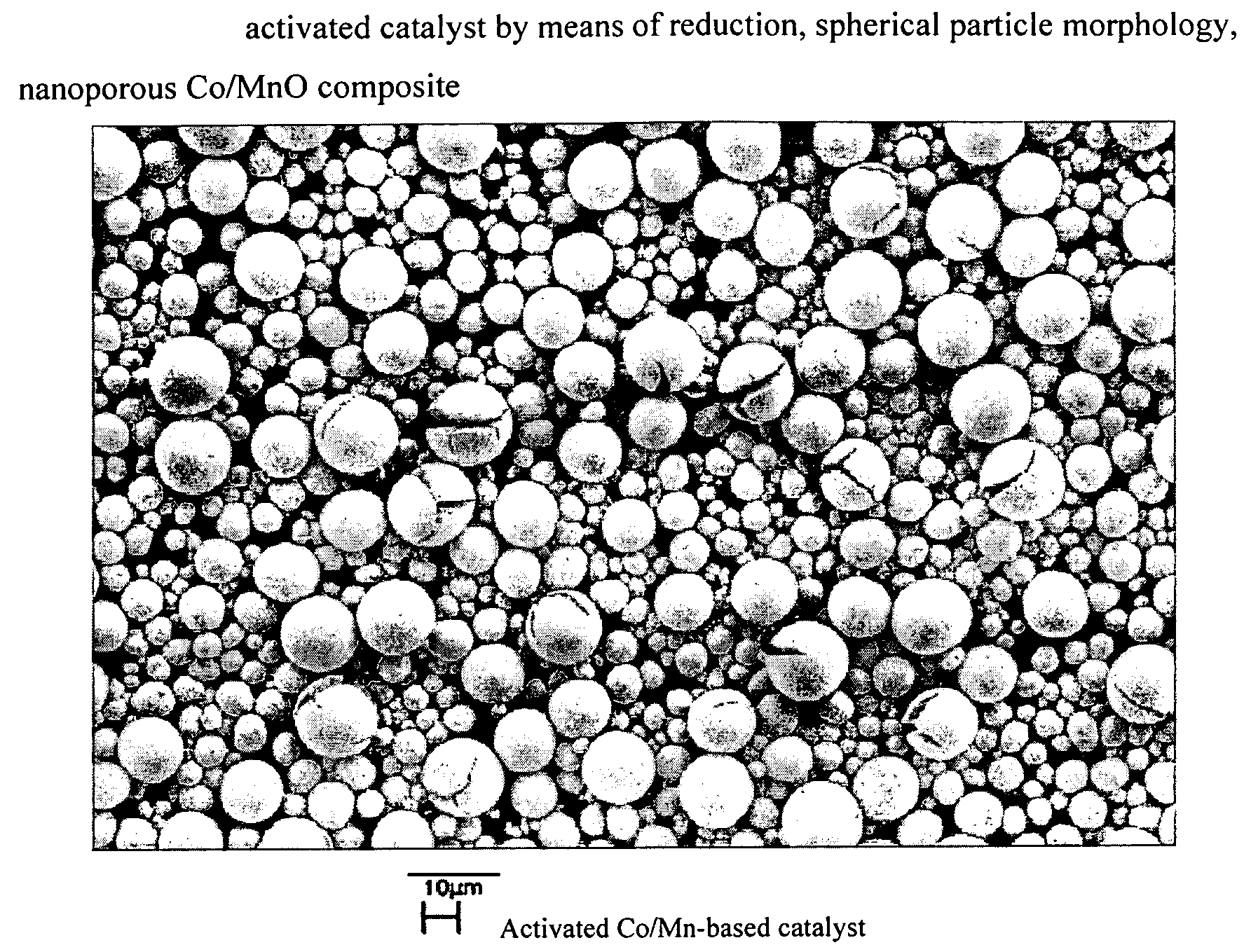
[0012]According to the present invention, it has been discovered that controlling the precursor growth structure makes it possible to preshape the pore structure for the actual catalyst grain.
[0020]Due to the clear definition of the secondary agglomerates and the possibility, through the selection of suitable catalyst morphologies, of producing specific forms of secondary agglomerates, the carbon nanoparticles that can be achieved using the nanoporous catalyst particles according to the present invention are more usable and optimizable in comparison to known carbon nanoparticles with respect to their technical reprocessing.

Problems solved by technology

As a rule, however, units produced in this way are not as stable as grown structures.
In addition, it is not as a rule possible to control the pore structure in the grain.
A fundamental difficulty in such catalyst / support systems, therefore, is the low controllability of microporosity and nanoporosity within the individual particles in combination with the size of the catalytically active components and the process technology-relevant external morphological properties such as particle size and particle shape.

Method used


Image

  • Nanoporous Catalyst Particles, the Production Thereof and Their Use
  • Nanoporous Catalyst Particles, the Production Thereof and Their Use
  • Nanoporous Catalyst Particles, the Production Thereof and Their Use

Examples


example 1

Manufacture of a Co / Mn-Based Catalyst and its use for the Manufacture of Spherical Aggregates Composed of Multiple-Walled Carbon Nanotubes

Manufacture of the Catalyst

[0045]The catalyst is manufactured through continuous combining of three educt solutions.

[0046]Solution I:[0047]3050 ml of a solution of 1172.28 g (NH4)2CO3 (stoichiometric) in demineralized water

[0048]Solution II:[0049]3130 ml of a solution of 960.4 g Co(NO3)2*6 H20 and 828.3 g Mn(NO3)2*4 H2O

[0050]Solution III:[0051]960 ml of a 10.46 mole ammonia solution

[0052]The individual solutions are simultaneously metered into a 1-liter reactor at a constant metering speed over a period of 24 h; this reactor permits an intensive, thorough mixing and is equipped with an overflow via which product suspension is continuously discharged. The precipitation reaction occurs at 50° C. After the first 20 h, the discharging of the product via the overflow is begun. The suspension has a deep blue-violet color. The solid is separated from the...

example 2

Manufacture of Multiple-Walled Carbon Nanotube Aggregates by means of a (Co,Mn)CO3 Catalyst

[0058]A catalyst according to example 1 is used without prior activation, directly for the manufacture of multiple-walled carbon nanotubes. The transformation into multiple-walled carbon nanotubes occurs as in example 1, without a prior reduction step. The product demonstrates a uniform distribution in the thickness of the nanotubes, as is clear from the REM images in FIGS. 5a, 5b, and 5c.

[0059]The TEM images in FIGS. 6a and 6b verify the presence of multiple-walled carbon nanotubes.

example 3

Manufacture of Multiple-Walled Carbon Nanotube Aggregates with Narrow Particle Distribution by means of a (Co,Mn)CO3 Catalyst

[0060]A catalyst according to example 1 is classed according to size by means of sieving and a particle size fraction of 20 μm-32 μm is used without prior activation, directly as a catalyst. FIGS. 7a and 7b show REM images of the catalyst sieve fraction used.

[0061]The transformation into multiple-walled carbon nanotubes takes place as in example 1.

[0062]This yields spherical aggregates composed of multiple-walled nanotubes with a narrow particle size distribution. With comparable transformation conditions, this makes it possible to adjust the size of the spherical carbon nanotube aggregates by means of the size of the catalyst particles. REM images of the product are shown at various magnifications in FIGS. 8a, 8b, 8c, and 8d.

[0063]The TEM images in FIGS. 9a and 9b confirm the presence of multiple-walled carbon nanotubes.


PUM

PropertyMeasurementUnit
temperaturesaaaaaaaaaa

Abstract

The invention relates to nanoporous catalyst particles having a spherical and / or spheroidal secondary structure, which contain, as catalytically active constituents, transition metals and / or oxides or precursors thereof. The invention also relates to a method for producing the nanoporous catalyst particles, during which, by means of a precipitation process, precursors with a spherical and / or spheroidal preliminary shape are produced from soluble compounds of the active constituents, and these morphologically pre-shaped precursors are, in a thermal activation step, transformed into nanoporous catalyst particles having a spherical and / or spheroidal secondary structure. The inventive catalyst particles can be used in the production of ceramic materials, as electrode materials in electrochemical cells or in fuel cells, as storage materials for chemical species and, in particular, in the production of carbon nanoparticles in the form of small tubes or fibers.

Description

FIELD OF THE INVENTION[0001]The present invention relates to nanoporous catalyst particles with a spherical and / or spheroidal secondary structure, the production thereof, and their use, particularly in the manufacture of carbon nanoparticles in the form of tubes or fibers.PRIOR ART[0002]Supported catalyst particles with active components in the nanoscale range are known. Catalyst / support systems based on Ni / Al2O3 can be produced, for example, through saturation of Al2O3 precursors with nickel salt solutions and subsequent reduction or decomposition of nickel-containing aluminum hydroxides or oxides and reduction of the nickel.[0003]It is possible to shape such systems by means of spray agglomeration. As a rule, however, units produced in this way are not as stable as grown structures. Frequently, the use of binding agents is required. In addition, it is not as a rule possible to control the pore structure in the grain.[0004]A fundamental difficulty in such catalyst / support systems, ...

Claims


Application Information

Patent Timeline
Patent Type & Authority Applications(United States)
IPC IPC(8): B01J21/18B01J23/32B01J23/755C04B35/00D01F9/12B01J23/75B01J23/745
CPCB01J23/8892B01J35/08B01J35/10C01B2202/06B82Y30/00B82Y40/00C01B31/0233B01J37/03C01B32/162Y02E60/50B01J35/393B01J35/30B01J35/23B01J35/51B01J23/889B01J35/60
Inventor AXMANN, PETERWOHLFAHRT-MEHRENS, MARGRETKASPER, MICHAELWEIRATHER, WOLFGANG
Owner ZENT FUR SONNENENERGIE & WASSERSTOFF FORSCHUNG BADEN WURTTEMBERG GEMEINNUTZIGE STIFTUNG
Learn More