Eureka AIR delivers breakthrough ideas for toughest innovation challenges, trusted by R&D personnel around the world.

Liquid Crystal Display and Substrate Thereof

a technology of liquid crystal display and substrate, which is applied in the direction of static indicating devices, instruments, non-linear optics, etc., can solve the problems of data line defects, such as breakage and the like, and achieve the effects of reducing parasitic capacitance, reducing parasitic capacitance, and increasing signal transmission quality

Active Publication Date: 2009-02-05
KUSN INFOVISION OPTOELECTRONICS
View PDF8 Cites 21 Cited by
  • Summary
  • Abstract
  • Description
  • Claims
  • Application Information

AI Technical Summary

Benefits of technology

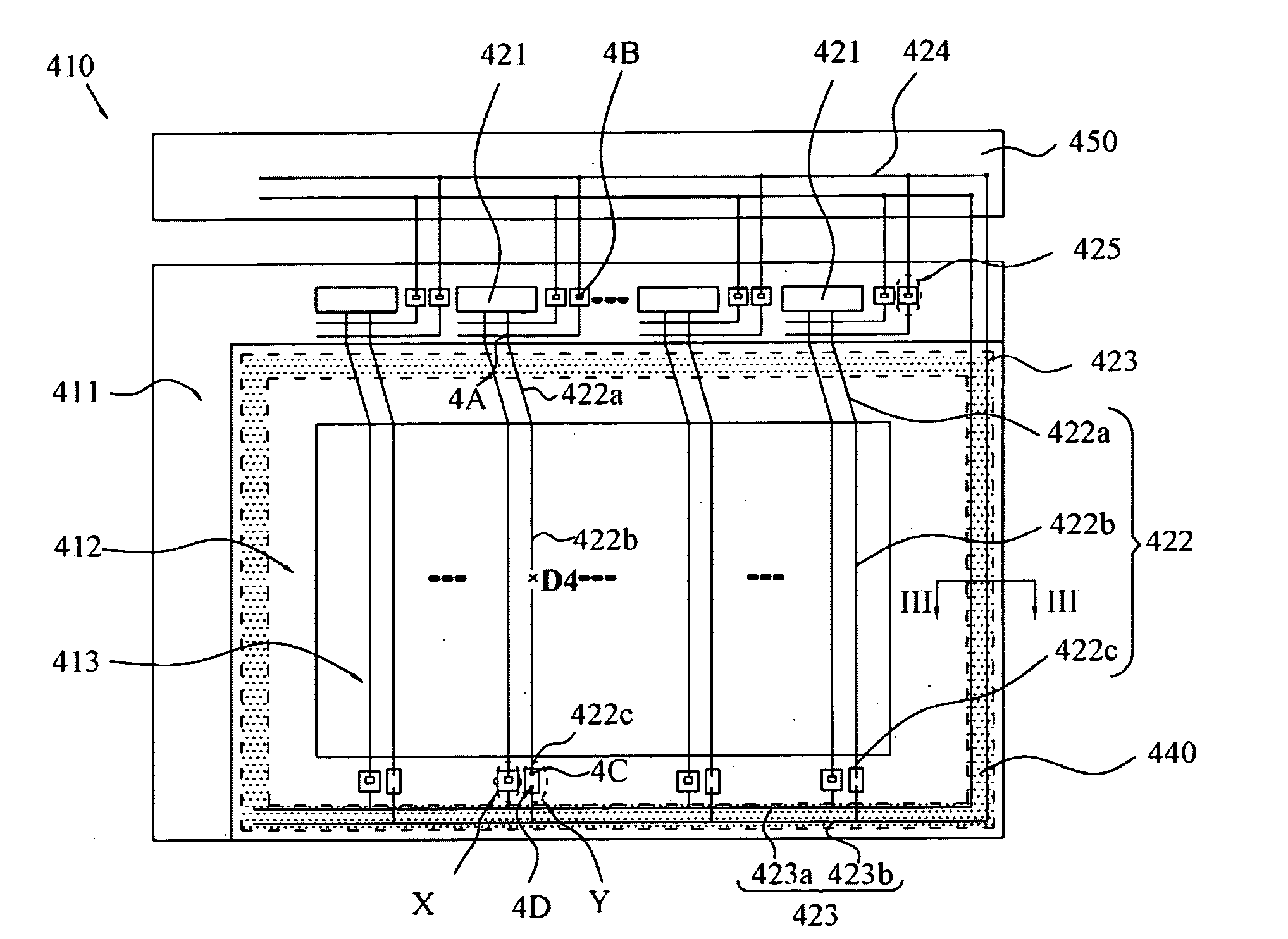
[0010]According to an embodiment of the invention, the repair lines of the repair circuit are positioned in different layers such that the parasitic capacitance between the repair lines of the repair circuit is significantly reduced. Moreover, the repair lines may be placed substantially right beneath an adhesive sealing so as to reduce the parasitic capacitance between the repair circuit and the transparent common electrode in the liquid crystal display, resulting in an increased signal transmission quality. In addition, the liquid crystal display may further comprise a printed circuit board separately, and the repair lines can be partially formed on the printed circuit board instead of on the array substrate, thus a material having a high electric conductivity such as copper can be used and the resistance of the repair circuit can be reduced.

Problems solved by technology

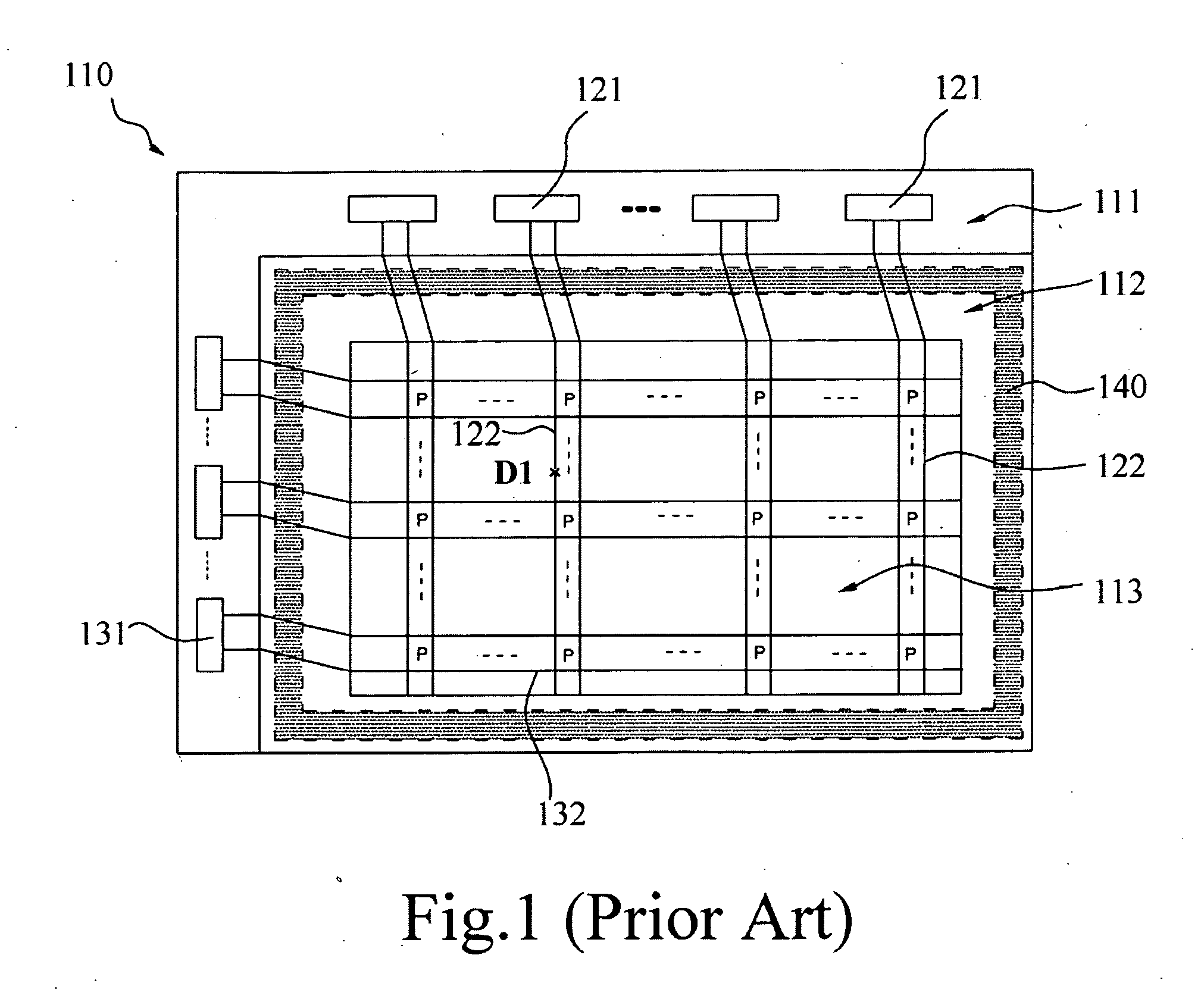
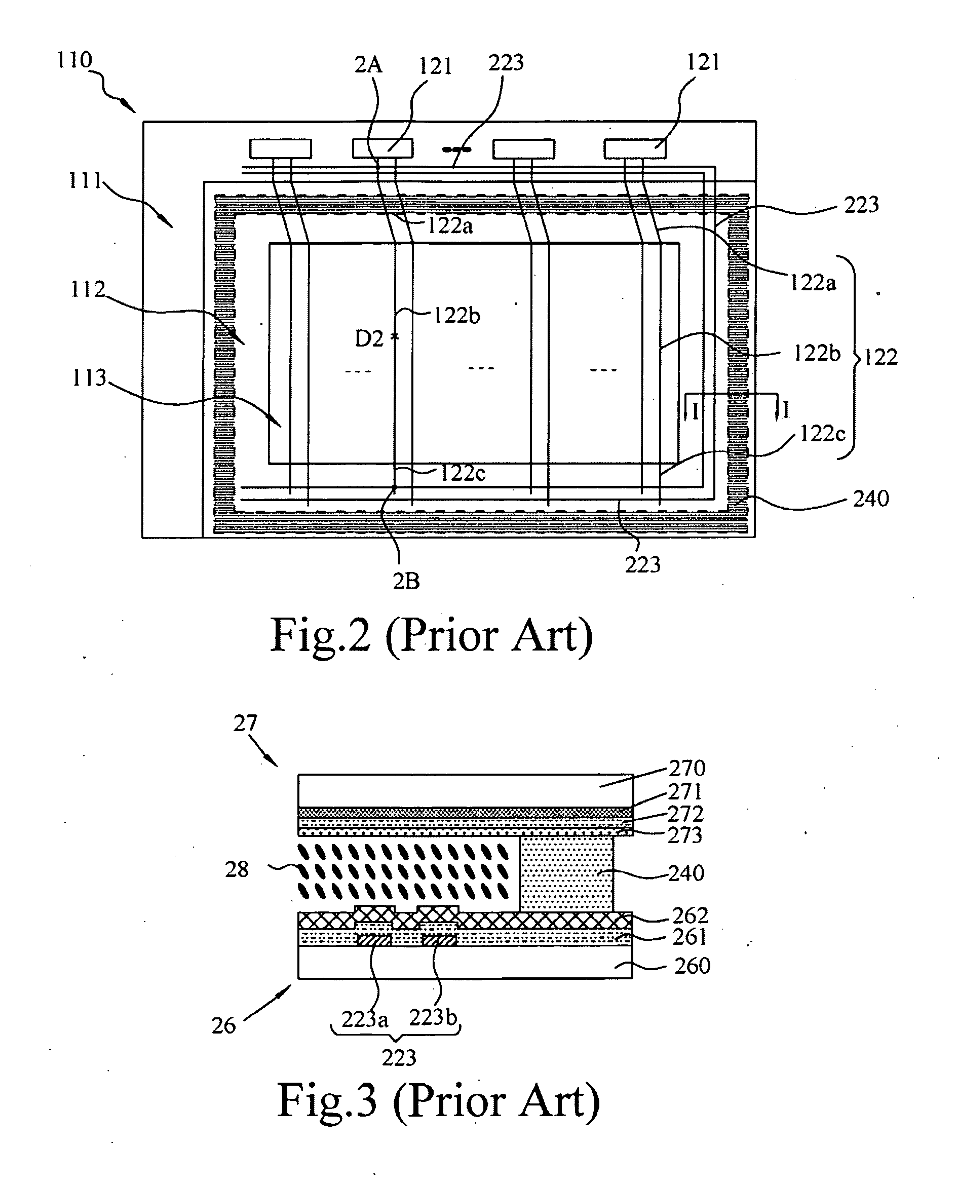
In manufacturing processes for conventional LCD array substrates, defects such as a break and the like may occur in the data lines.
In this case, a data signal cannot be transmitted to the data line below the break D1, thereby causing a so-called line defect.

Method used


Image

  • Liquid Crystal Display and Substrate Thereof
  • Liquid Crystal Display and Substrate Thereof
  • Liquid Crystal Display and Substrate Thereof

Examples


Embodiment Construction

[0022]Exemplary embodiments will be described in detail in the following with reference to the drawings.

[0023]FIG. 4 is a plan view showing a repair circuit structure of an LCD array substrate in accordance with a first embodiment of the invention. The LCD array substrate 410 comprises a display region 413 and a signal introducing region 411. A plurality of data line pads 421 is formed in the signal introducing region 411 and electrically connected with corresponding data lines 422 respectively. Each of the data lines 422 comprises three portions, that is, a front data line portion 422a outside the display region 413 and electrically connected with a corresponding data line pad 421, a display region data line portion 422b in the display region 413, and an end data line portion 422c outside the display region 413 and at the side away from the data line pad 421. A data signal inputted from the data line pad 421 is transmitted through the entire data line 422 from the front data line p...


PUM

PropertyMeasurementUnit
lengthaaaaaaaaaa
power consumptionaaaaaaaaaa
defectaaaaaaaaaa

Abstract

A liquid crystal display having a repair circuit structure and an array substrate of the liquid crystal display are provided. Each of the repair lines of the repair circuit comprises a front repair line portion arranged to cross with a front data line portion in a substantially perpendicular manner, an end repair line portion arranged to cross with an end data line portion in a substantially perpendicular manner, and an intermediate repair line portion connecting the front and end repair line portions. At least two repair lines in the end repair line portion are positioned in different layers so that a parasitic capacitance between respective repair lines in the repair circuit structure can be reduced and signal transmission quality can be ensured.

Description

TECHNICAL FIELD [0001]The present invention relates to a liquid crystal display (LCD) and an array substrate thereof, and in particular to a liquid crystal display having repair line structure.TECHNICAL BACKGROUNDS [0002]Liquid crystal displays (LCDs) are advantageous in being light, thin and having low power consumption. They are being widely used in modern information devices such as notebook computers, mobile phones, and personal digital assistants (PDAs).[0003]FIG. 1 shows an array substrate of a conventional liquid crystal display. The LCD array substrate 110 comprises a signal introducing region 111 and a display region 113. Data line pads 121 and scanning line pads 131 are formed in the signal introducing region 111. A plurality of data lines 122 and scanning lines 132 are respectively connected to the data line pads 121 and the scanning line pads 131. A plurality of pixels P is defined in a region where the data lines and the scanning lines cross. A data signal and a scannin...

Claims


Application Information

Patent Timeline
Patent Type & Authority Applications(United States)
IPC IPC(8): G02F1/133
CPCG02F1/136259G02F2001/136272G09G2330/08G09G2300/0426G09G2320/0219G09G3/3648G02F1/136272
Inventor CHUNG, TE-CHENJEN, TEAN-SEN
Owner KUSN INFOVISION OPTOELECTRONICS
Why Eureka
Eureka Blog
Learn More