Power supply apparatus and high-frequency circuit system
a technology of power supply apparatus and high-frequency circuit, which is applied in the direction of oscillator generators, electric discharge tubes, travelling-wave tubes, etc., can solve the problems of increasing the overall cost of the high-frequency circuit system comprising the traveling-wave tubes and the power supply apparatus, reducing safety when performing such work, and requiring time, etc., to achieve simple configuration, low cost, and shorten the effect of discharging tim
- Summary
- Abstract
- Description
- Claims
- Application Information
AI Technical Summary
Benefits of technology
Problems solved by technology
Method used
Image
Examples
first exemplary embodiment
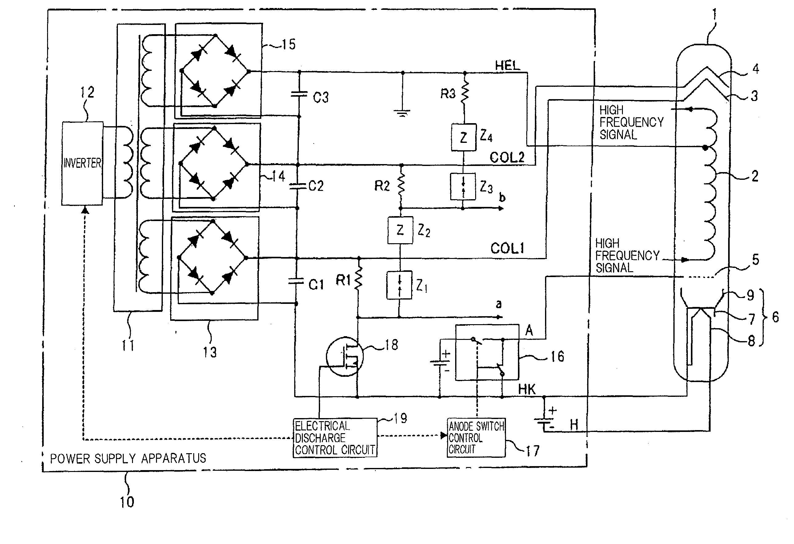
[0047]FIG. 3 is a block diagram that illustrates the configuration of a high-frequency circuit system according to a first exemplary embodiment.
[0048]As illustrated in FIG. 3, a high-frequency circuit system according to the first exemplary embodiment includes traveling-wave tube 1 and power supply apparatus 10 that supplies a predetermined DC voltage (power supply voltage) to each electrode of traveling-wave tube 1.
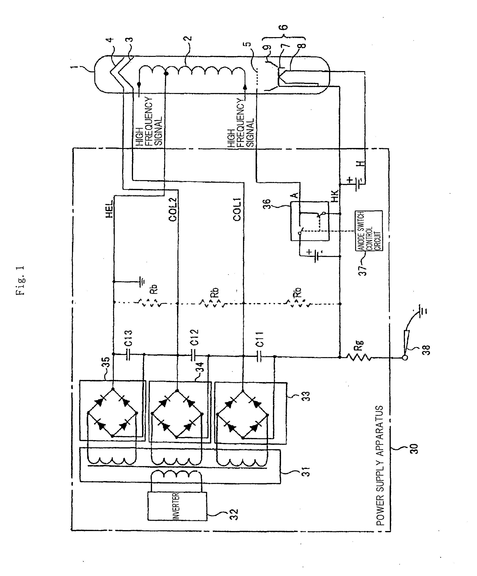
[0049]Traveling-wave tube 1 shown in FIG. 3 comprises two collector electrodes (first collector electrode 3 and second collector electrode 4), similarly to traveling-wave tube 1 shown in FIG. 1. The remaining configuration is the same as that of traveling-wave tube 1 shown in FIG. 1, and therefore will not be described in detail below. Power supply apparatus 10 shown in FIG. 3 is an example of a configuration that supplies two kinds of collector voltages (first collector voltage (COL1) and second collector voltage (COL2)) to traveling-wave tube 1 comprising two collector...
second exemplary embodiment
[0081]FIG. 5 is a block diagram that illustrates the configuration of a high-frequency circuit system according to a second exemplary embodiment.
[0082]As shown in FIG. 5, power supply apparatus 20 of the second exemplary embodiment differs from the power supply apparatus of the first exemplary embodiment in the respect that second arrester Z3, second varistor Z4 and resistor R3 that are connected in series are connected between the helix (ground potential) and connection node a of electrical discharge switch 18 and resistor R1.
[0083]Similarly to the first exemplary embodiment, the power supply apparatus of the second exemplary embodiment can discharge electric charges accumulated in rectifier capacitors C1 to C3 even without first varistor Z2 and second varistor Z4 shown in FIG. 5. According to the power supply apparatus of the second exemplary embodiment, when traveling-wave tube 1 comprises three or more collector electrodes, it is sufficient that electrical discharge switch 18 an...
PUM
 Abstract
Description
Claims
Application Information
 - R&D
- Intellectual Property
- Life Sciences
- Materials
- Tech Scout
- Unparalleled Data Quality
- Higher Quality Content
- 60% Fewer Hallucinations
Browse by: Latest US Patents, China's latest patents, Technical Efficacy Thesaurus, Application Domain, Technology Topic, Popular Technical Reports.
© 2025 PatSnap. All rights reserved.Legal|Privacy policy|Modern Slavery Act Transparency Statement|Sitemap|About US| Contact US: help@patsnap.com


