
Device and method for photolysis-assisted electrolysis

Inactive Publication Date: 2009-02-05
BRICOLEUR PARTNERS LP
View PDF0 Cites 7 Cited by
  • Summary
  • Abstract
  • Description
  • Claims
  • Application Information

AI Technical Summary

Benefits of technology

[0010]In various embodiments disclosed herein, a device and method for photolysis-assisted electrolysis is disclosed that can operate both at high rates and efficiencies. The device and method use the three-dimensional quality of a fluidized bed to eliminate many of the limitations of a photolysis hydrogen generator. Moreover, the function of an electrolysis system is improved by assisting that reaction with electrons generated by the photolysis reaction. The result is a synergistic photolytic-electrolytic system that uses less electricity per amount of hydrogen produced, thereby improving the efficiency of either electrolysis and photolysis alone.

Problems solved by technology

Without further costly purification to remove CO and CO2, the hydrogen fuel cell cannot operate efficiently.
Conventional water electrolysis also has disadvantages, primarily inefficiency.
In many conventional devices, factors such as cell resistance, inefficient movement of electrolyte, and inefficient collection of reaction products from the electrolyte stream contribute to significant efficiency loss.
Low current operation increases efficiency, however, it also lowers the amount of hydrogen that can be produced at a given time because hydrogen production rate is directly proportional to the applied current.
Presently, the low efficiency of the water electrolysis process prevents this process from being a competitive alternative to steam reformation.
Photolysis is notoriously inefficient due to many physical design constraints including the need for the electrolyte to flow over the reactive surface without absorbing too much of the energy from the incoming photons.
Photolysis reactions, using conventional catalysts and device design, are generally not commercially feasible to produce a significant volume of product, for example hydrogen, from water.

Method used


Image

  • Device and method for photolysis-assisted electrolysis
  • Device and method for photolysis-assisted electrolysis
  • Device and method for photolysis-assisted electrolysis

Examples


Embodiment Construction

[0026]For purposes of summarizing the inventions and the advantages achieved over the prior art, certain items and advantages of the inventions are described herein. Of course, it is to be understood that not necessarily all such items or advantages may be achieved in accordance with any particular embodiment of the inventions. Thus, for example, those skilled in the art will recognize that the inventions may be embodied or carried out in a manner that achieves or optimizes one advantage or group of advantages as taught or suggested herein without necessarily achieving other advantages as may be taught or suggested herein.

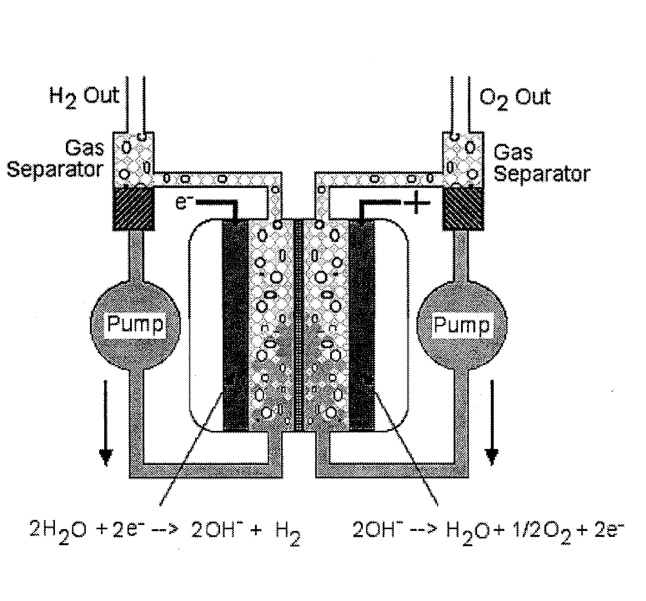
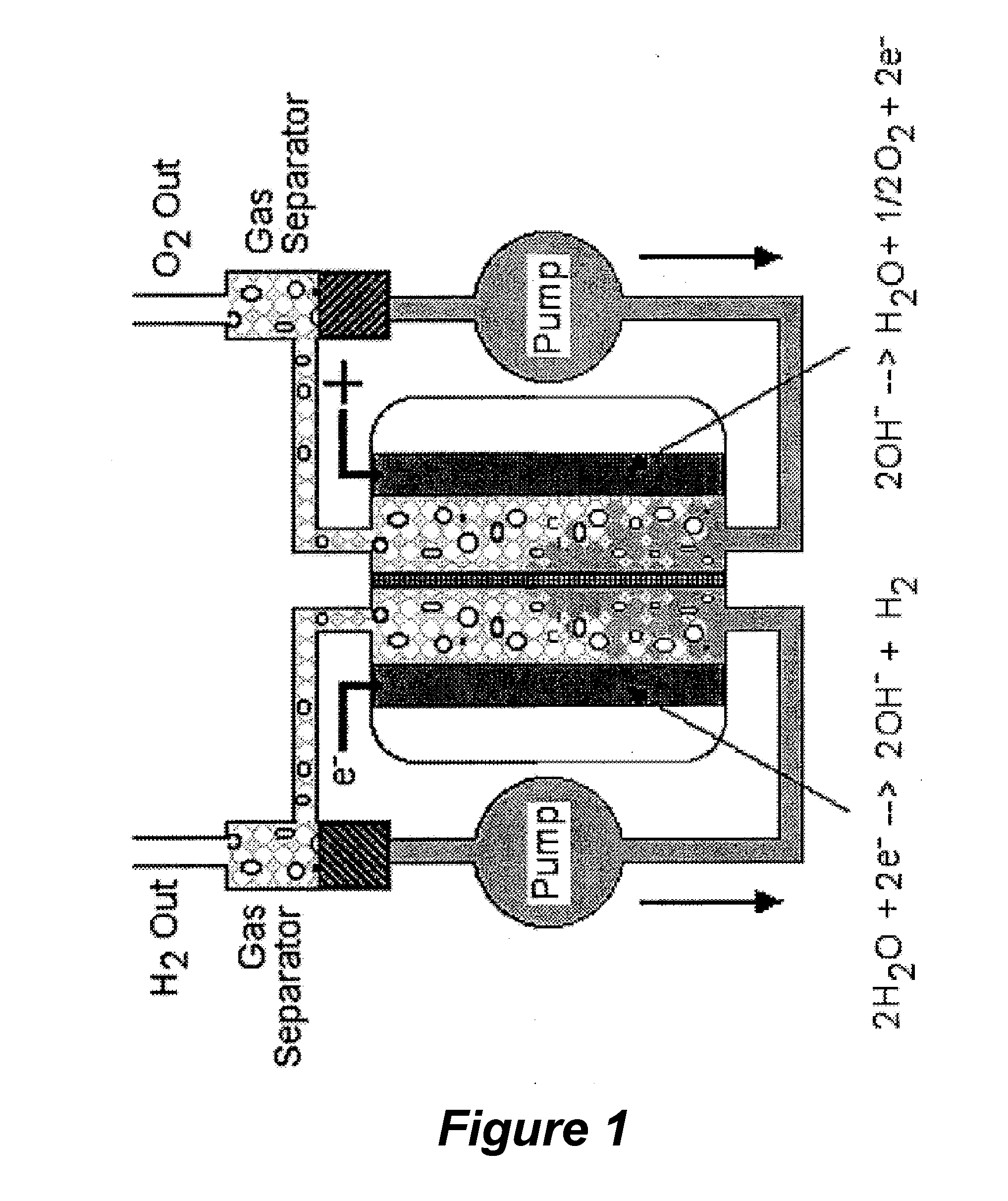
[0027]FIG. 1 illustrates a traditional water electrolysis system. The main features of this system are pumps circulating at the anode and cathode to remove resulting oxygen and hydrogen gasses, respectively. The electrodes are typically oriented in a vertical fashion and are substantially solid, typically metal or electrodeposited metal with relatively low surface ...


PUM

PropertyMeasurementUnit
Fractionaaaaaaaaaa
Fractionaaaaaaaaaa
Diameteraaaaaaaaaa

Abstract

A photolysis-assisted electrolysis device comprises at least one fluidized bed disposed in the device's housing wherein the fluidized bed comprises a reaction medium and photolysis-catalyzing nanoparticles suspended in the reaction medium. When the fluidized bed is exposed to light, the nanoparticles catalyze the photolysis of the reaction medium to form donor electrons. The donor electrons promote reduction of the reaction medium during an electrolysis reaction, for example, the reduction of water to form hydrogen gas.

Description

PRIORITY INFORMATION[0001]This application is based on and claims priority to U.S. Provisional Patent Application No. 60 / 915,619, filed May 2, 2007, the entire contents of which are hereby expressly incorporated by reference.BACKGROUND[0002]1. Technical Field[0003]The inventions disclosed herein generally relate to photochemical and electrochemical reactions for electrolysis.[0004]2. Description of the Related Art[0005]Hydrogen is a renewable fuel that produces zero emissions when used in a fuel cell. In 2005, the Department of Energy (DoE) developed a new hydrogen cost goal and methodology, namely to achieve $2.00-3.00 / gasoline gallon equivalent (gge, delivered, untaxed, by 2015), independent of the pathway used to produce and deliver hydrogen.[0006]Today, the principal method to produce hydrogen is steam reformation. Nearly 95% of the hydrogen presently being produced is made by steam reformation, where natural gas is reacted on metallic catalyst at high temperature and pressure. ...

Claims


Application Information

Patent Timeline
IPC IPC(8): C01B3/02
CPCY02E60/368C25B1/003C25B1/55Y02E60/36
Inventor DOPP, ROBERT BRIANMCGRATH, KIMBERLY
Owner BRICOLEUR PARTNERS LP
Learn More