
Article with visual code, visual code generating apparatus and information conveying method

Inactive Publication Date: 2013-01-03
TSUJI SUSUMU
View PDF3 Cites 6 Cited by
  • Summary
  • Abstract
  • Description
  • Claims
  • Application Information

AI Technical Summary

Benefits of technology

The present invention allows for better conveying of messages and information using devices with optical reading function such as scanners. This improves the way information is conveyed.

Problems solved by technology

However, a barcode cannot convey any message through visual observation by a human.
When a human simply see a two-dimensional code, the arrangement of dots in the two-dimensional code looks like a mere random pattern, and he or she cannot recognize any meaningful message from the two-dimensional code.
It is undesirable that a barcode or a two-dimensional code attached to or printed on an article is not attractive at all for consumers or the like who directly see the article, and it is also undesirable that attaching a barcode or a two-dimensional code makes the design of an article worse.
Further, since neither a barcode nor a two-dimensional code provides any message that can be visually recognized by a human, the opportunity or the place to attach a barcode or a two-dimensional code to an article is restricted depending on the ways or forms of the utilization of the article.
For instance, it is undesirable that a barcode or a two-dimensional code is arranged in a noticeable part of an article that is displayed in public, such as the front face, the central part of the article.
Also, in the case of an article with a small surface area, it is difficult to secure an area to attach a barcode or a two-dimensional code in the article, in addition to the area where the name of the article and the name of the manufacturer of the article are printed.

Method used


Image

  • Article with visual code, visual code generating apparatus and information conveying method
  • Article with visual code, visual code generating apparatus and information conveying method
  • Article with visual code, visual code generating apparatus and information conveying method

Examples


Embodiment Construction

[0036]Embodiments of the present invention will be described below, referring to the drawings.

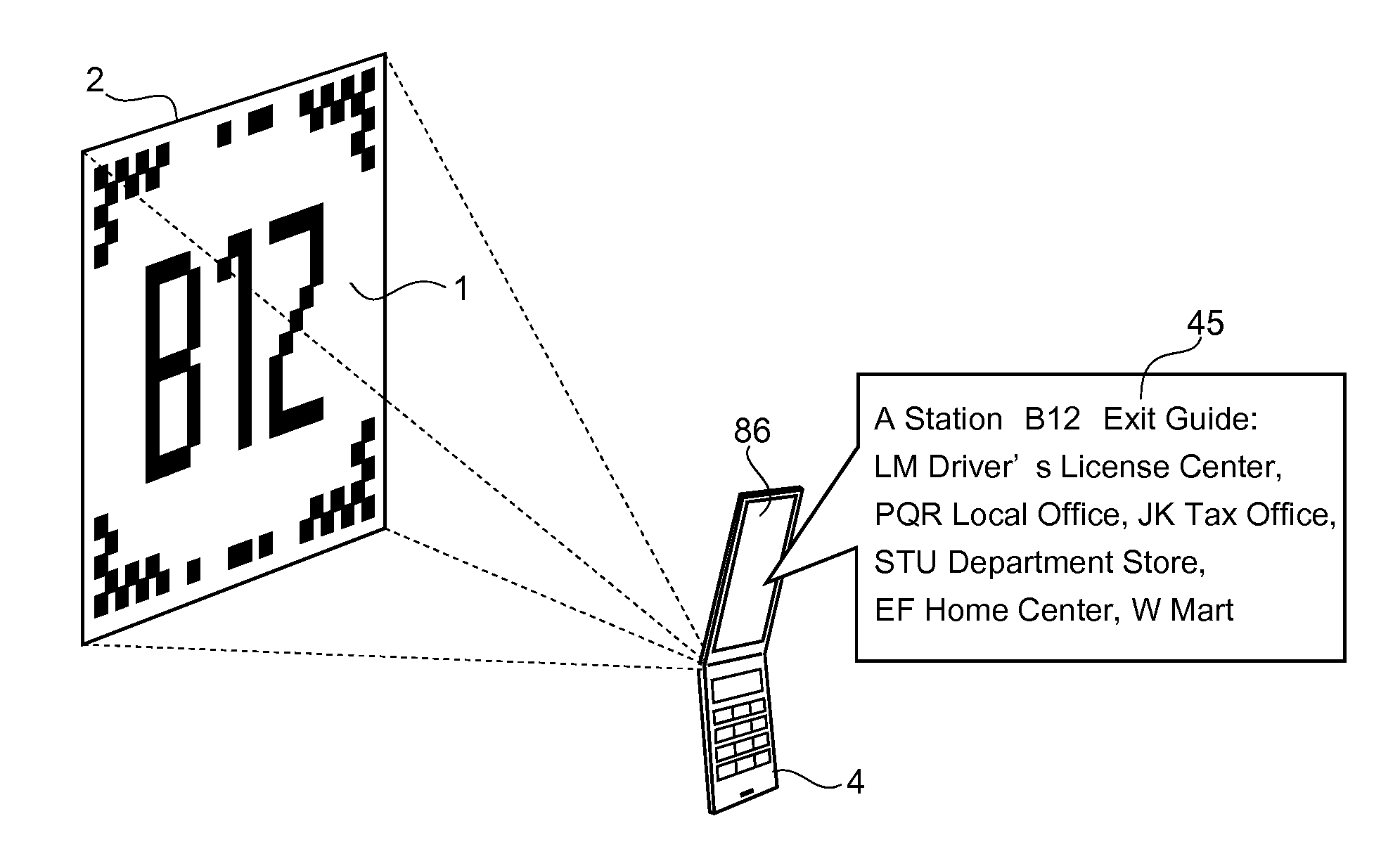
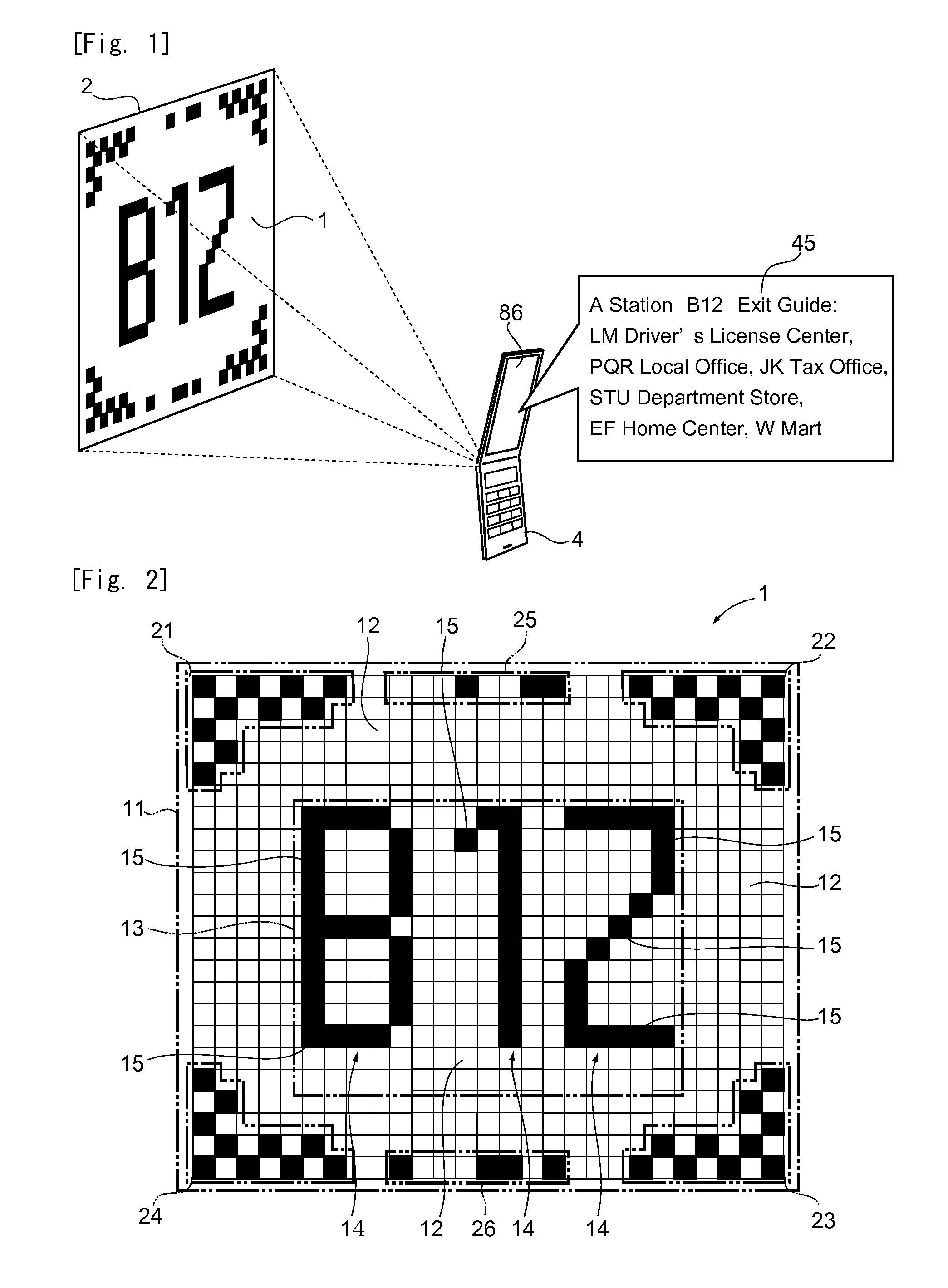
[0037](Outline of Information Conveyance) FIG. 1 shows the outline of the information conveyance by an article having a visual code according to an embodiment of the present invention. In FIG. 1, information conveyance is carried out by an article having a visual code 1 according to an embodiment of the present invention as follows.

[0038]First, the visual code 1 is generated by a visual code generating apparatus. The visual code 1 is a code formed by making a link between a symbol arrangement pattern, which can be visually recognized as a message by a human and can be recognized by an apparatus with an optical reading function, and linked information 45 that is different from the message. In the example shown in FIG. 1, the symbol arrangement pattern in the visual code 1 expresses “B12” as a message. This message B12 indicates a subway exit number. Also, in the example shown in FIG. 1, the ...


PUM


Abstract

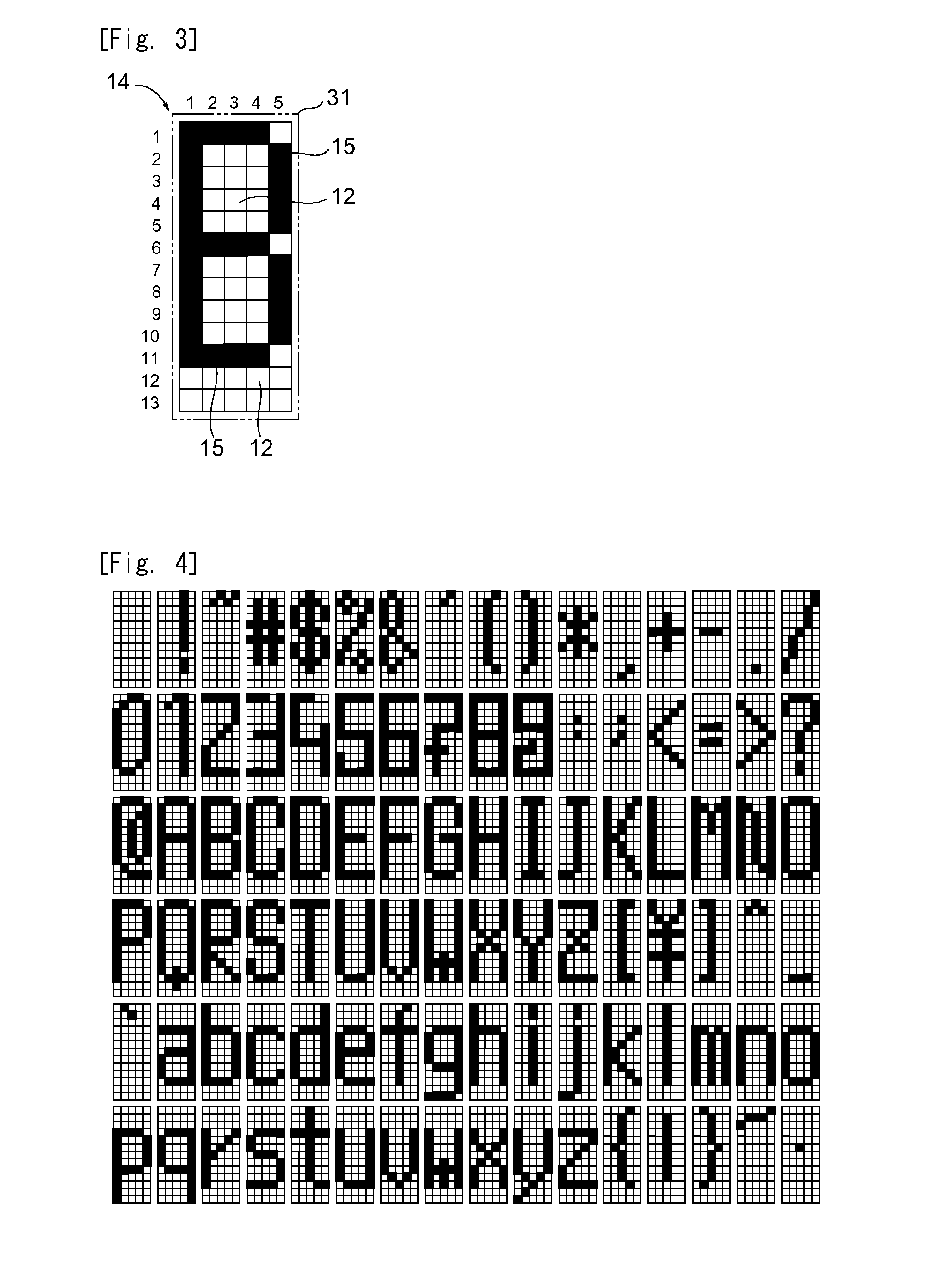
An article having a visual code that can visually and directly convey a message to a human and accurately and indirectly convey information through an apparatus with an optical reading function. Visual code 1 is attached to an article. In visual code 1, symbol arrangement pattern 13, which indicates a message that can be visually recognized by a human, is formed by forming code space 11 by arranged multiple regions 12 in a grid, selecting one or more than one region 12 from among multiple regions 12 in code space 11, and placing pattern element 15 in each of selected regions 12. Each region 12 where pattern element 15 is placed so as to form symbol arrangement pattern 13 among multiple regions 12 in code space 11 indicates ON; each region 12 where pattern element 15 is not placed indicates OFF.

Description

TECHNICAL FIELD[0001]The present invention relates to an article with a visual code that can visually and directly convey a message to a human, and can indirectly convey information different from the message to a human by using an apparatus having an optical reading function; a visual code generating apparatus for generating such a visual code; and an information conveying method for directly and visually conveying a message, and indirectly conveying information different from the message by using an apparatus having an optical reading function.BACKGROUND ART[0002]At present, the technique of attaching or printing a barcode to an article (or a product), and inputting the information on the article into a cash register or a computer used for managing articles, by reading the barcode with a reading apparatus having a scanner has been widely spread (see patent document 1). A barcode used for such a technique typically represents numbers or characters by varying the widths of lines arr...

Claims


Application Information

Patent Timeline
IPC IPC(8): G06K19/06G06F17/30G06V30/224
CPCG06K19/06G09F3/00G06K7/10G06V30/224
Inventor TSUJI, SUSUMU
Owner TSUJI SUSUMU
Learn More