
Partial discharge detection device

a detection device and partial discharge technology, applied in the direction of fault location, line-transmission details, instruments, etc., can solve the problems of difficult retrofitting of internal detectors, difficult to detect electromagnetic waves, and damage that will develop into a serious accident, so as to reduce the effect of external noise, simple constitution, and simple device structur

Inactive Publication Date: 2009-01-29
KK TOSHIBA
View PDF2 Cites 34 Cited by
  • Summary
  • Abstract
  • Description
  • Claims
  • Application Information

AI Technical Summary

Benefits of technology

[0022]The present invention was proposed to resolve the problems confronted by conventional technologies such as those mentioned above and an object of the present invention is to provide a high-performance partial discharge detection device which is user-friendly and compact and which allows detection of the electromagnetic waves caused by partial discharge, over a wide bandwidth with a simple constitution and a favorable S / N ratio.
[0024]According to the present invention with a constitution of this kind, when electromagnetic waves generated in accordance with partial discharge propagate within a hermetically sealed metal container, the receiving means receives electromagnetic waves which leak from the insulator. Here, because the opening in the waveguide of the receiving means is open opposite the insulator, the effects of external noise can be suppressed and electromagnetic waves can be received as a result of the waveguide portion itself acting as an electromagnetic wave detection antenna.
[0025]Therefore, the detected electromagnetic waves can be sent to the signal processing means by using a coaxial cable attached to a coaxial cable connector and, after signal processing on the electromagnetic waves has been performed by the signal processing means, the signal processing determination means is able to judge whether partial discharge exists. Furthermore, in the partial discharge detection device of the present invention, the waveguide portion is used as the electromagnetic wave receiving means, and therefore, an antenna with a simple constitution can be constituted. Hence, it is easy to attach the receiving means outside the metal container and a simplification of the device structure is possible.
[0026]According to the present invention, by employing receiving means which comprises a waveguide portion and a coaxial cable connector as an electromagnetic wave detection antenna, a high-performance partial discharge detection device can be provided which is user-friendly and compact and which allows detection of the electromagnetic waves caused by partial discharge, over a wide bandwidth and with a favorable S / N ratio.

Problems solved by technology

When partial discharge in a gas-insulated equipment is neglected, before long insulation damage is incurred and there is the danger that the damage will develop into a serious accident.
Hence, it has proven difficult to retro-fit an internal detector 27 to a gas-insulated equipment which does not have the internal detector 27 attached beforehand and hard to detect electromagnetic waves.
However, the following problems with these methods were noted.
Further, because the impedance is discontinuous, the detection sensitivity of both methods was low and there was a high susceptibility to the effects of external noise.
Hence, the S / N ratio was inadequate and the partial discharge could not be detected highly accurately.
Moreover, in the case of a rectangular waveguide, the cut-off frequency is decided by the shape of the waveguide and the wavelength of the electromagnetic waves propagated by the long side dimension of the waveguide is constrained, meaning that propagation of electromagnetic waves of wavelengths equal to or more than two times the long side dimension of the waveguide cross-section is inefficient.
Therefore, the coaxial waveguide converter shown in FIGS. 6 and 7 has a large form and, when the form is integrated in a partial discharge detection device, this has the inconvenience of enlarging the device.

Method used


Image

  • Partial discharge detection device
  • Partial discharge detection device
  • Partial discharge detection device

Examples


Embodiment Construction

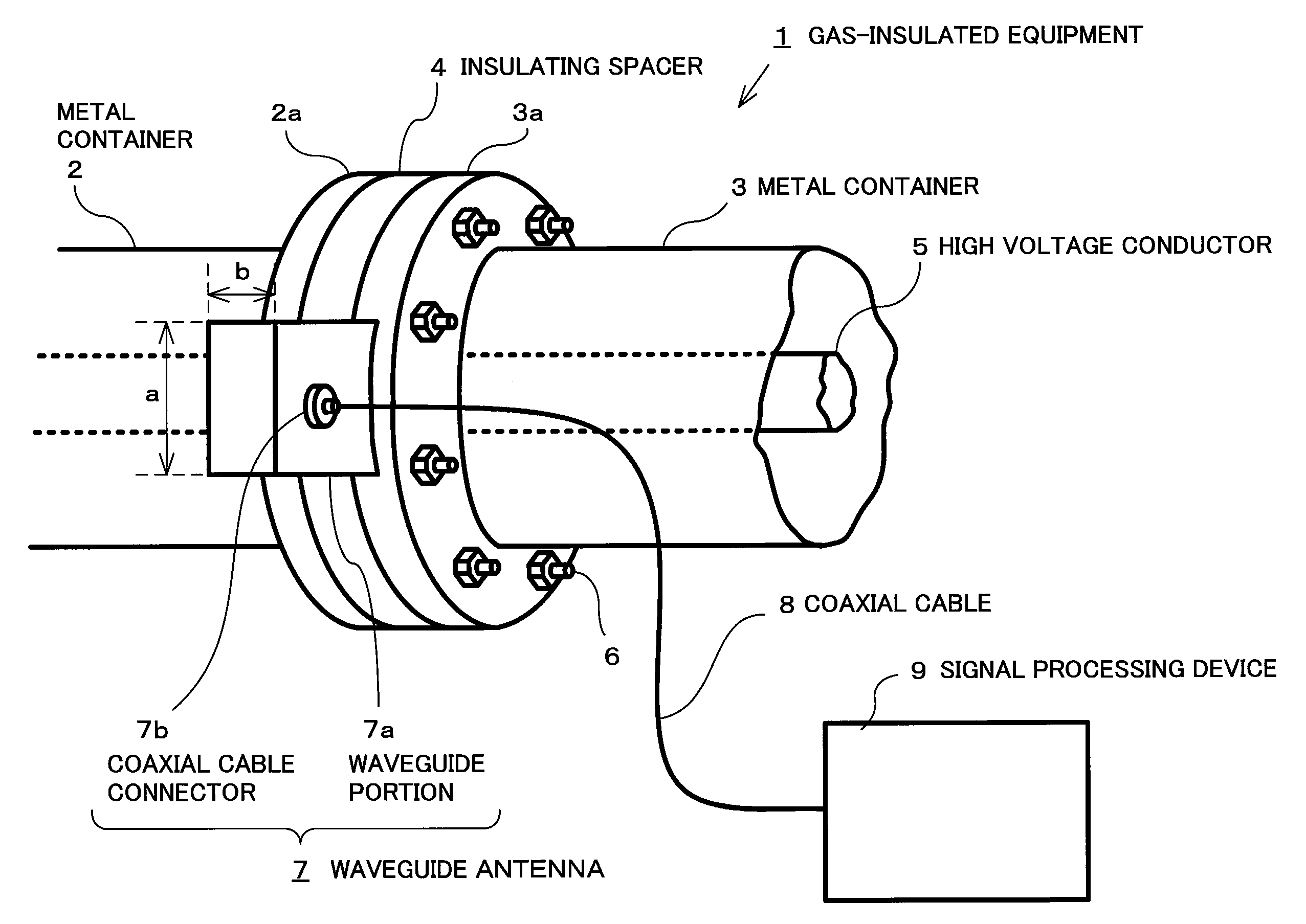
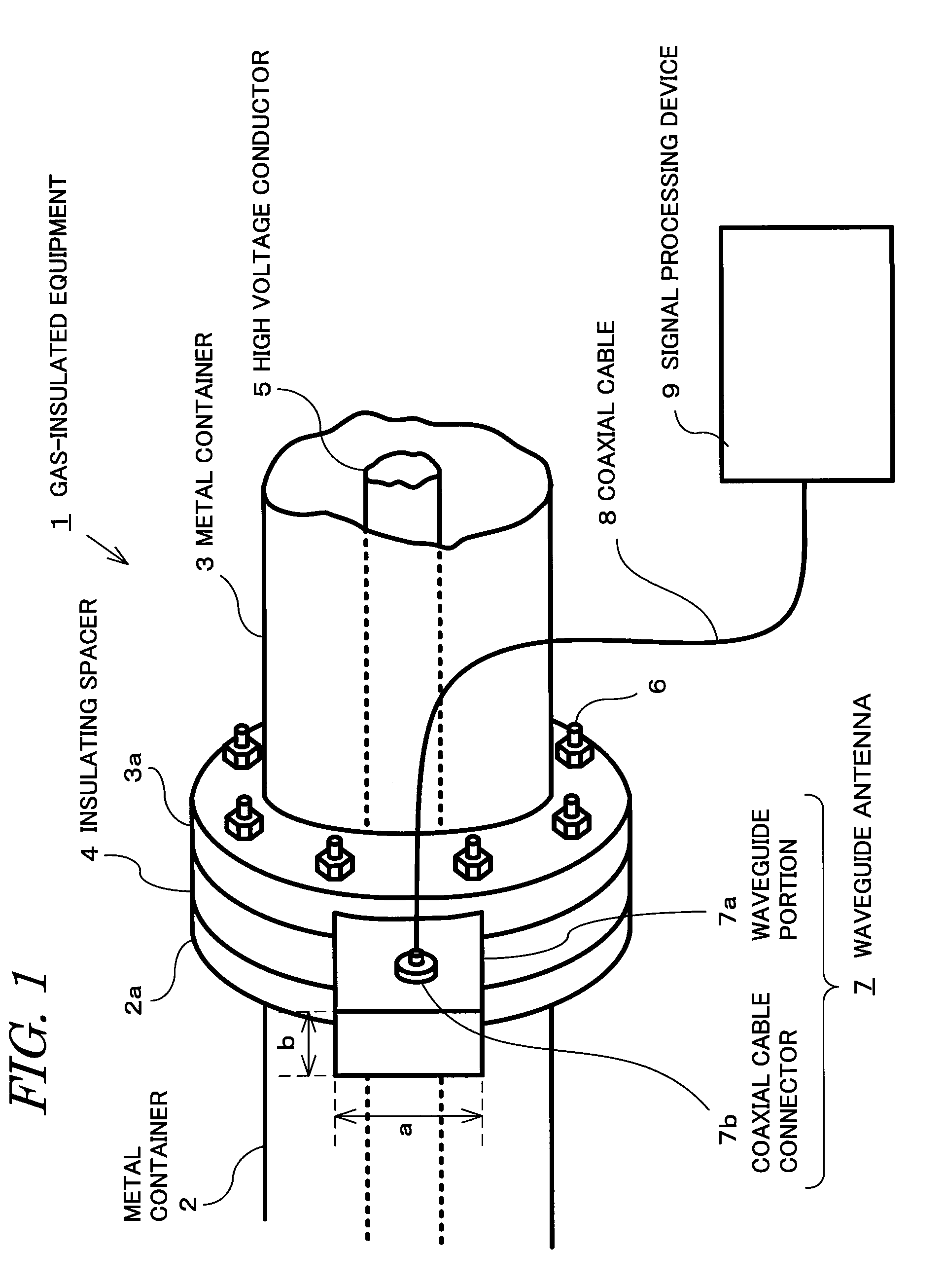
[0034]A representative embodiment of the present invention will be specifically described hereinbelow with reference to FIGS. 1 to 3. This embodiment is a partial discharge detection device that detects partial discharge by determining electromagnetic waves which are generated in a gas-insulated equipment in the same manner as the conventional technology shown in FIG. 5.

(1) Constitution of this Embodiment

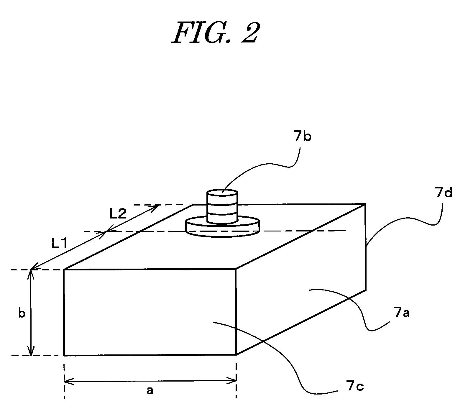
[0035]FIG. 1 is a constitutional view including a perspective view of a gas-insulated equipment to which this embodiment is applied and FIG. 2 is a perspective view of the receiving means according to this embodiment. The gas-insulated equipment 1 has a high voltage conductor 5 inserted in hermetically sealed metal containers 2 and 3 which are charged with an insulating gas and the high voltage conductor 5 is supported by an insulating spacer 4 which is an insulator. The circumference of the insulating spacer 4 is sandwiched between flange portions 2a and 3a of the metal containers ...


PUM


Abstract

The present invention provides a high-performance partial discharge detection device which is user-friendly and compact and which allows detection of the electromagnetic waves caused by partial discharge, over a wide bandwidth with a simple constitution and a favorable S / N ratio. The waveguide antenna which receives electromagnetic waves that leak from the insulating spacer is attached to the outer circumferential face of the insulating spacer. The waveguide antenna is constituted by a waveguide portion and a coaxial cable connector which is installed on the waveguide portion. The waveguide portion has a metal short-circuit plate provided at one end thereof, and an opening formed at the other end thereof, which covers part of the outer circumferential face of the insulating spacer.

Description

BACKGROUND OF THE INVENTION[0001]1. Field of the Invention[0002]The present invention relates to a partial discharge detection device that detects partial discharge which is generated in a gas-insulated equipment, and more particularly to a partial discharge detection device which is capable of detecting, with high sensitivity, electromagnetic waves caused by the partial discharge generation.[0003]2. Description of the Related Art[0004]Generally, gas-insulated equipments such as gas-insulated switchgears, gas-insulated generating lines, and gas-insulated transformers are employed in transformer substations. Gas-insulated equipments are devices in which a high voltage conductor is housed in a hermetically sealed metal container which is charged with an insulating gas and supported by means of an insulator. It is known that, in a gas-insulated equipment, when there is a defective part with which there is poor contact in the metal container or which is invaded by a metallic foreign bod...

Claims


Application Information

Patent Timeline
Patent Type & Authority Applications(United States)
IPC IPC(8): G01R31/02
CPCG01R31/1254G01R31/12
Inventor MARUYAMA, SHIROSAKAKIBARA, TAKAAKIHOSHINO, TOSHIHIRO
Owner KK TOSHIBA
Learn More