
Shading protection for solar cells and solar cell modules

Inactive Publication Date: 2009-01-29
DAY4 ENERGY
View PDF6 Cites 68 Cited by
  • Summary
  • Abstract
  • Description
  • Claims
  • Application Information

AI Technical Summary

Benefits of technology

[0034]In accordance with another aspect of the invention, there is provided a method for protecting a solar cell against effects caused by shading, in a solar cell system. The method involves electrically coupling a back side current collector of a bypass diode to a front side of the solar cell and electrically coupling a front side current collector of the bypass diode to a back side current collector of the solar cell to enable a current generated by non-shaded solar cells in the solar cell system to be shunted through the bypass diode when the solar cell is shaded. The method also involves disposing the bypass diode closely adjacent the back side current collector of the solar cell and thermally coupling the bypass diode to the back side current collector of the solar cell such that heat generated in the bypass diode due to current shunted through the bypass diode is dissipated by the solar cell sufficiently to avoid burning the solar cell or the bypass diode when the solar cell is shaded.
[0038]The method may involve causing a second oppositely facing surface of the first bus bar to generally face away from the back side of the solar cell.
[0046]In accordance with another aspect of the invention, there is provided a use of at least a portion of a first solar cell as a bypass diode for a second solar cell, where the second solar cell is series connected to other solar cells a system of solar cells, by electrically coupling a back side current collector of the at least a portion of the first solar cell to a front side current collector of the second solar cell and electrically coupling a front side current collector of the at least a portion of the first solar cell to a back side current collector of the second solar cell to enable a current generated by non-shaded solar cells in the system to be shunted through the at least a portion of the first solar cell when the second solar cell is shaded. There is also provided a use for disposing the bypass diode closely adjacent the back side current collector and thermally coupling the at least a portion of the first solar cell to the back side of the second solar cell such that heat generated in the at least a portion of the first solar cell due to current shunted through the at least a portion of the first solar cell is dissipated by the second solar cell sufficiently to avoid burning the at least a portion of the first solar cell or the second solar cell when the second solar cell is shaded.
[0047]In accordance with another aspect of the invention, there is provided a method of protecting a solar cell against shading in a system of series-connected solar cells exposed to light. The method involves electrically coupling a back side current collector of at least a portion of a first solar cell configured to act as a bypass diode to a front side current collector of a second solar cell configured to convert light energy into electrical energy, wherein the second solar cell is series connected to other solar cells in the system, where the other solar cells are configured to convert light energy into electrical energy. The method also involves electrically coupling a front side current collector of the at least a portion of the first solar cell to a back side current collector of the second solar cell such that a current generated by non-shaded solar cells in the system is shunted through the at least a portion of the first solar cell when the second solar cell is shaded. The method further involves disposing the bypass diode closely adjacent the back side current collector of the solar cell. The method also involves thermally coupling the at least a portion of the first solar cell to the back side of the second solar cell such that heat generated in the at least a portion of the first solar cell due to current shunted through the at least a portion of the first solar cell is dissipated by the second solar cell sufficiently to avoid burning the at least a portion of the first solar cell or the second solar cell when the second solar cell is shaded.

Problems solved by technology

However, if even one PV cell within the module is shaded, while all other cells are illuminated, the overall efficiency of the entire PV module is strongly affected, resulting in a substantial decrease in power output from the PV module.
In addition, the module may be permanently damaged as a result of cell shading.
These high temperatures may eventually damage the shaded PV cell and destroy the entire PV module.
While bypassing individual cells has been known for many years, and several patents have been issued, several economical and technical problems have impeded the introduction of a practical industrial solution.
The production of such cells is complicated and requires precision alignment between the screen printed current collecting electrode and the bypass diode portion.
Furthermore the techniques disclosed would not be practical for modern high efficient crystalline silicon PV cells because thin film bypass diodes can not withstand high currents such as about 8.5 A which is a typical current value in a high efficiency 6 inch cell.
Furthermore, there appears to be no regard for dissipation of heat that is generated in the bypass diode which could cause overheating and eventually cause the diode to fail and may possibly lead to the destruction of the PV cell and the PV module.
The production methods described are complicated and require precision grooves to be cut in the solar cell.
The grooves can make the solar cell fragile, increasing cell breakage and yield losses.
Again, the techniques described in this reference would not be practical for modern high efficient crystalline silicon PV cells because thin film bypass diodes generally can not withstand the high currents typically found with such cells, or the resultant heating caused by such high currents.
Again, the techniques described in the above two patents require complicated and costly microelectronic technological approaches not easily incorporated into a production line and the bypass diodes created would likely not be able to withstand the high current and resulting heat that can occur when the bypass diode is required to conduct current.
In addition, the amorphous semiconductor bypass diode cannot withstand the high currents and resulting temperatures that can occur in crystalline silicon solar cell systems.
Although bypass diodes with such a small width and length may be able to carry relatively large currents, due to their small area they tend to heat up due to current flow and impose a localized extreme heat source on the solar cell to which they are mounted.

Method used


Image

  • Shading protection for solar cells and solar cell modules
  • Shading protection for solar cells and solar cell modules
  • Shading protection for solar cells and solar cell modules

Examples


Embodiment Construction

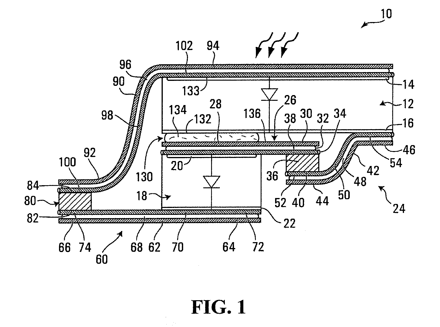
[0075]Referring to FIG. 1, a shading protected solar cell apparatus for use in a solar cell system is shown generally at 10. The apparatus 10 includes a solar cell shown generally at 12 having a front side current collector 14 and a back side current collector 16. The front side current collector 14 may include a plurality of screen-printed metallized fingers (not shown) on the front surface of the solar cell 12 and the back side current collector 16 may include a screen printed aluminum metallization layer such as conventionally provided on silicon crystalline solar cells. The front side current collector may include transparent conductive coating such as InOx, SnOx or ZnOx or spattered or evaporated aluminum metallized patterns and the back side current collector may include laser fired contacts or spattered aluminum, or a transparent conductive coating such as InOx, SnOx or ZnOx.

[0076]The apparatus 10 further includes a bypass diode shown generally at 18 disposed closely adjacent...


PUM


Abstract

In accordance with one aspect of the invention, there is provided a shading protected solar cell apparatus for use in a solar cell system. The apparatus includes a solar cell having a front side current collector and a back side current collector. The apparatus also includes a bypass diode closely adjacent the back side current collector, the bypass diode having a front side current collector and a back side current collector. The apparatus further includes a first electrical coupling for electrically coupling the front side current collector of the bypass diode to the back side current collector of the solar cell. The apparatus also includes a second electrical coupling for electrically coupling the back side current collector of the bypass diode to the front side current collector of the solar cell, the first and second electrical couplings cooperating to enable a current generated by non-shaded solar cells in the system to be shunted through the bypass diode when the solar cell is shaded. The apparatus further includes a thermal coupling thermally coupling the bypass diode to a back side of the solar cell such that heat generated in the bypass diode due to current shunted through the bypass diode is dissipated by the solar cell sufficiently to avoid burning the solar cell or the bypass diode when the solar cell is shaded.

Description

BACKGROUND OF THE INVENTION[0001]1. Field of Invention[0002]This invention relates to photovoltaic (PV) cells, in particular, protecting a PV cell and / or PV module against overheating caused by shading or other light obstruction to a PV cell when used as one of a plurality of series-connected PV cells in a PV module.[0003]2. Description of Related Art[0004]A typical PV cell comprises semiconductor material with at least one p-n junction and front and back side surfaces equipped with current collecting electrodes. When illuminated, the cell generates a voltage of approximately 0.6-0.62 V and an electric current of about 34 mA / cm2. A plurality of PV cells may be electrically connected in series and / or in parallel arrays to form PV modules that produce higher voltages and / or higher currents. A PV module only performs at optimal efficiency when all the series-connected PV cells are illuminated with approximately similar light intensity. However, if even one PV cell within the module is ...

Claims


Application Information

Patent Timeline
IPC IPC(8): H01L31/052H01L31/05
CPCY02E10/50H02S40/34H01L31/0512H01L27/1421
Inventor RUBIN, LEONIDSADLIK, BRAMNEBUSOV, VALERYOSIPOV, ALEXANDERSCHNEIDER, ANDREASTARASENKO, VASILY
Owner DAY4 ENERGY
Learn More