
Light path circuit apparatus and ring laser gyro

a light path circuit and laser gyro technology, applied in the direction of speed measurement using gyroscopic effects, instruments, surveying and navigation, etc., can solve the problems of inconvenient use, device size is too large, vibration type gyro is not suited for absolute angle detection, etc., to achieve easy angular velocity detection and low cost

Inactive Publication Date: 2009-01-22
RICOH KK
View PDF5 Cites 9 Cited by
  • Summary
  • Abstract
  • Description
  • Claims
  • Application Information

AI Technical Summary

Benefits of technology

[0008]An object of the present invention is to provide a new light path circuit apparatus that can be produced at low cost and is suited to a small sized ring laser gyro. In addition, a further object of the present invention is to provide a new light path circuit apparatus that is able to easily perform angular velocity detection in more than two axial directions and furthermore, a ring laser gyro using these light path circuit apparatuses.

Problems solved by technology

A vibration type gyro is not suited for detection of absolute angles because the zero point offset is large.
Although optical fiber gyros or a ring lasers gyro have high performance, they are not suited to consumer use because of their comparatively large size and high price.
When performing angular velocity detection in more than two axial directions, if a light path circuit part described in JP3751553A is used, it is necessary to combine two or more light path circuit parts used for the detection of each of the axial directions and the device thus becomes too large in size.
In addition, when combining two light path circuit parts used for angular velocity detection in one axial direction, it is difficult to ensure that the two parts are mutually orthogonal at the time of assembly.

Method used


Image

  • Light path circuit apparatus and ring laser gyro
  • Light path circuit apparatus and ring laser gyro
  • Light path circuit apparatus and ring laser gyro

Examples


Embodiment Construction

[0035]Preferred embodiments of the present invention will be explained in detail hereinafter with reference to the accompanying drawings.

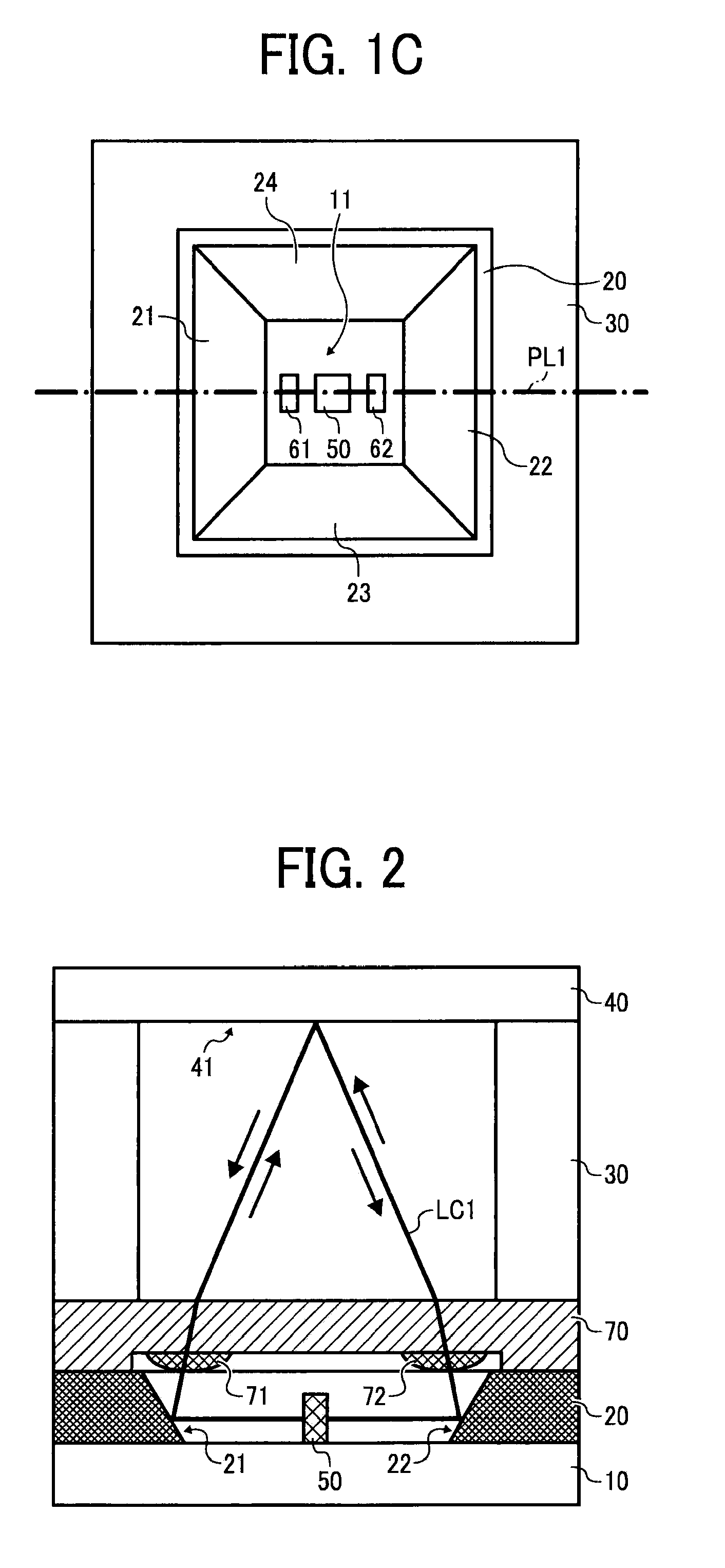
[0036]FIG. 1 illustrates an embodiment of the light path circuit apparatus.

[0037]FIG. 1A is a cross-sectional diagram of the light path circuit apparatus. FIG 1B is a cross-sectional diagram along the b-b line of FIG 1A. FIG. 1C is a cross-sectional diagram along the c-c line of FIG 1A. FIG 1A, FIG. 1B and FIG. 1C are all schematic diagrams. A hatch or the like that illustrates the cross-section is suitably abbreviated. In addition, because FIG 1A, FIG. 1B and FIG. 1C are all schematic diagrams, it should be noted that the ratio of the size of each part or the like is not precise. This is also true for the following figures. To exemplify the size of the light path circuit apparatus illustrated in FIG. 1, the size in the up and down, left and right direction of FIG. 1A˜1C is about a couple of millimeters.

[0038]In FIG 1A, reference numeral 10 illustr...


PUM


Abstract

A light path circuit apparatus suited for a small sized ring laser gyro, includes a base having a standard plane, one or more substrates laminated parallel against the standard plane in a direction orthogonal to the standard plane, a light source, wherein on the base and / or the one or more substrates, 3 or more reflective surfaces, having normal lines within a prescribed one plane orthogonal to the standard plane, are constituted parallel or with tilt by a prescribed angle to the standard plane, the light source is disposed to emit light within the prescribed one plane, and the light emitted from the light source circulates within the one plane in a forward and backward direction by three or more reflective surfaces and constitutes a light path circuit that laser oscillates.

Description

PRIORITY CLAIM[0001]This application is based on and claims priority from Japanese Patent Application No. 2007-182578, filed on Jul. 11, 2007, the disclosure of which is incorporated herein by reference in its entirety.BACKGROUND OF THE INVENTION[0002]1. Field of the invention[0003]The present invention relates to a light path circuit apparatus and a ring laser gyro.[0004]2. Description of the Related Art[0005]An angular velocity sensor has applications in many fields such as car navigation, vibration correction of cameras, video games, air planes, rockets and robots and so on. As an angular velocity sensor, a vibration type is conventionally known that lets an object vibrate by piezoelectricity or electrostatic force and calculates the angular velocity by detecting the Coriolis force generated, or an optical fiber gyro or a ring laser gyro that utilizes Sagnac effects.[0006]A vibration type gyro is not suited for detection of absolute angles because the zero point offset is large. ...

Claims


Application Information

Patent Timeline
IPC IPC(8): G01C19/66
CPCG01C19/66
Inventor AKANUMA, GOICHIMAENAKA, KAZUSUKEFUJITA, TAKAYUKI
Owner RICOH KK
Learn More