
Foam Rigidized Inflatable Structural Assemblies

a technology of rigidized and inflatable structures, applied in the field of inflatable, rigidized and deployable structures, can solve the problems of not fully addressed, raabe does not provide a gas escape mechanism to relieve, and provides uniform rigidization, so as to facilitate work and reduce length

Inactive Publication Date: 2009-01-22
NASA
View PDF39 Cites 17 Cited by
  • Summary
  • Abstract
  • Description
  • Claims
  • Application Information

AI Technical Summary

Benefits of technology

[0013]One embodiment of the present invention provides a rigidizable fluid and a container for the fluid. The container or containment member has at least one outer wall forming a closed vessel. The containment member further includes at least one opening and at least one exhaust port. The rigidizable fluid is injected, potentially though an injection port, or poured into the containment member through an opening. As the rigidizable fluid becomes rigid, it may release gases creating a pressure barrier. The pressure barrier may prevent the rigidizable fluid from advancing throughout the structure. In order to address this problem, excess pressure in the containment member can be exhausted through at least one exhaust port. If there is more than one outer wall, the innermost wall forms the containment member and the outermost wall may be a protective layer. The outermost wall may be selected to protect the structure against puncture from debris, rocks, meteors and the like, or from harmful radiation. The outer wall thickness may be selected for such properties as stiffness and strength or other desirable characteristics.
[0014]In an alternative embodiment, the structure further includes an inflatable bladder. The bladder is attached to the containment member and has at least one pressurizing port. The bladder can be inflated through the pressurizing port. Inflation of the bladder member also erects the containment member and gives the structure its shape prior to rigidization. The bladder member may be inflated with any gas or liquid. In the case of a biosphere, such as a habitat, the bladder provides a space that can support living organisms.
[0015]Another embodiment of the present invention provides a method for erecting and rigidizing a structure having an inflatable bladder attached to a containment member. The containment member includes at least one inner wall and at least one outer wall. First, the bladder is inflated to erect the structure. Then rigidizable fluid is introduced uniformly into the containment member between the inner wall and the outer wall by pouring or injection. The rigidizable fluid advances throughout the containment member and may release gas as it cures. The released gas is vented from the containment member to prevent the released gas from impeding the uniform distribution of injected rigidizable fluid.
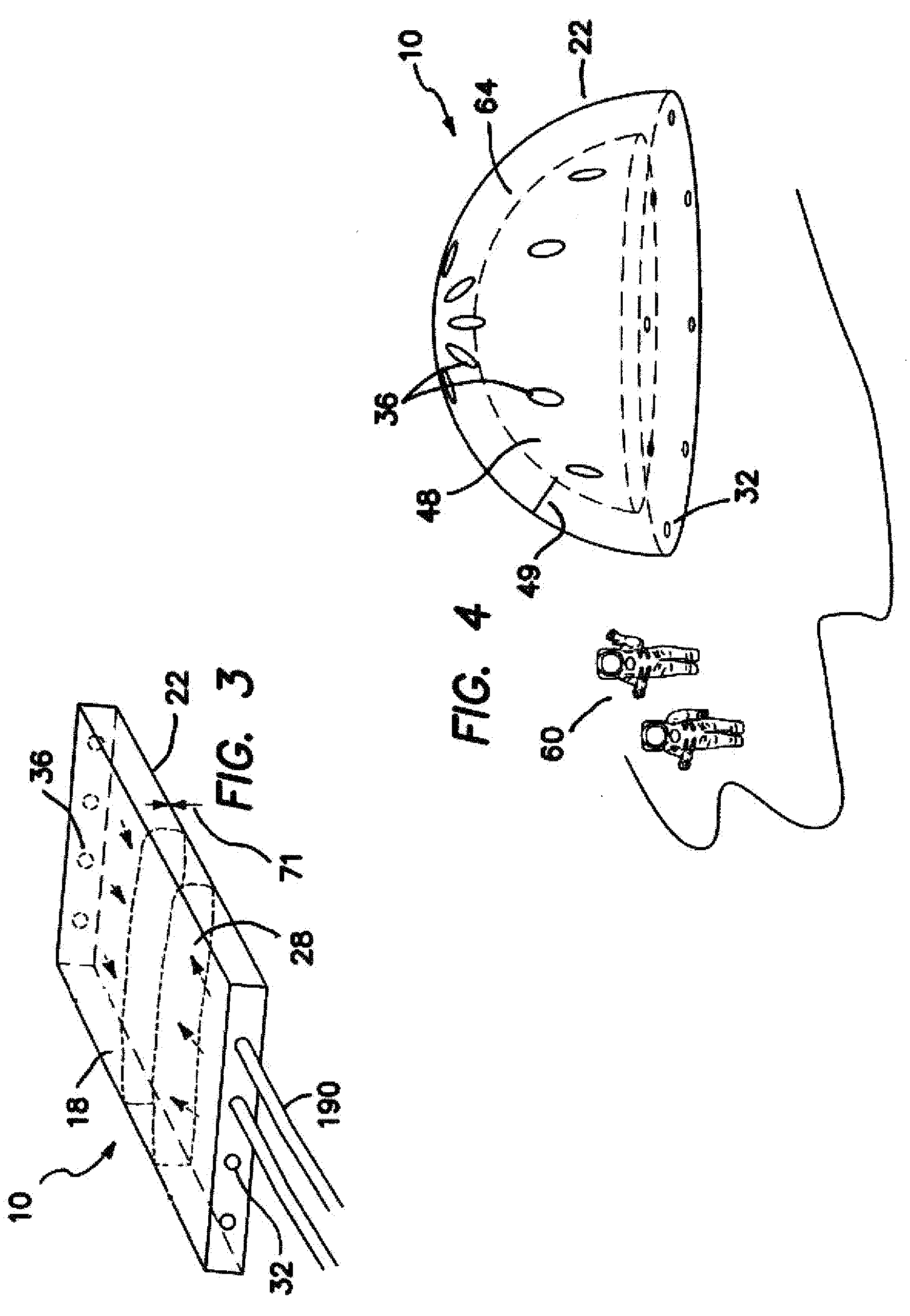
[0017]In another embodiment, the present invention provides a method for fabricating a tubular wall as follows: A tubular mold with a predetermined cross-section, a predetermined perimeter, and a predetermined length is selected. A section of flexible material with a predetermined length, and a width greater than the predetermined perimeter is also selected. It should be noted that a length shorter than the tubular mold may be selected, and such reduced length would facilitate ease of work. The width of flexible material is wrapped around the tubular mold and the two ends of the width are secured together forming a seam. The tubular mold is removed leaving a tubular wall having a first end and a second end. In another variant of the method, the tubular mold selected is a section of PVC pipe. In another embodiment, the present invention includes a plurality of rigidizable fluid containment areas and a network of transfer hoses, wherein the structure takes the form of a useful article selected from the group comprising: an enclosed storage structure including at least one movable door. The structure may be an enclosed dwelling structure including at least one door and at least one window, a support for equipment including a base and at least one component not in the plane of the base, and / or an open topped fluid container. Additional forms include a truss structure consisting of numerous tubular inflatable and rigidizable members, or alternatively the arrangement comprising a toroidal structure and tubular support structures, wherein the toroid can support a Fresnel lens, parabolic reflector or lens, or other components, and a framework for supporting advertising displays, aircraft wings and spacecraft appendages, wherein appendages may include solar panels.

Problems solved by technology

One problem which has not been fully addressed is the issue of providing uniform rigidization throughout the structure, particularly when larger structures or assembled structures are constructed.
However, Raabe does not provide a gas escape mechanism to relieve out gassing of the rigidizable material.
Nor does Raabe address the issue of uniform injection of rigidizable material.
Nor does Voelker address the issue of distributing foam uniformly throughout the double walls.

Method used


Image

  • Foam Rigidized Inflatable Structural Assemblies
  • Foam Rigidized Inflatable Structural Assemblies
  • Foam Rigidized Inflatable Structural Assemblies

Examples


Embodiment Construction

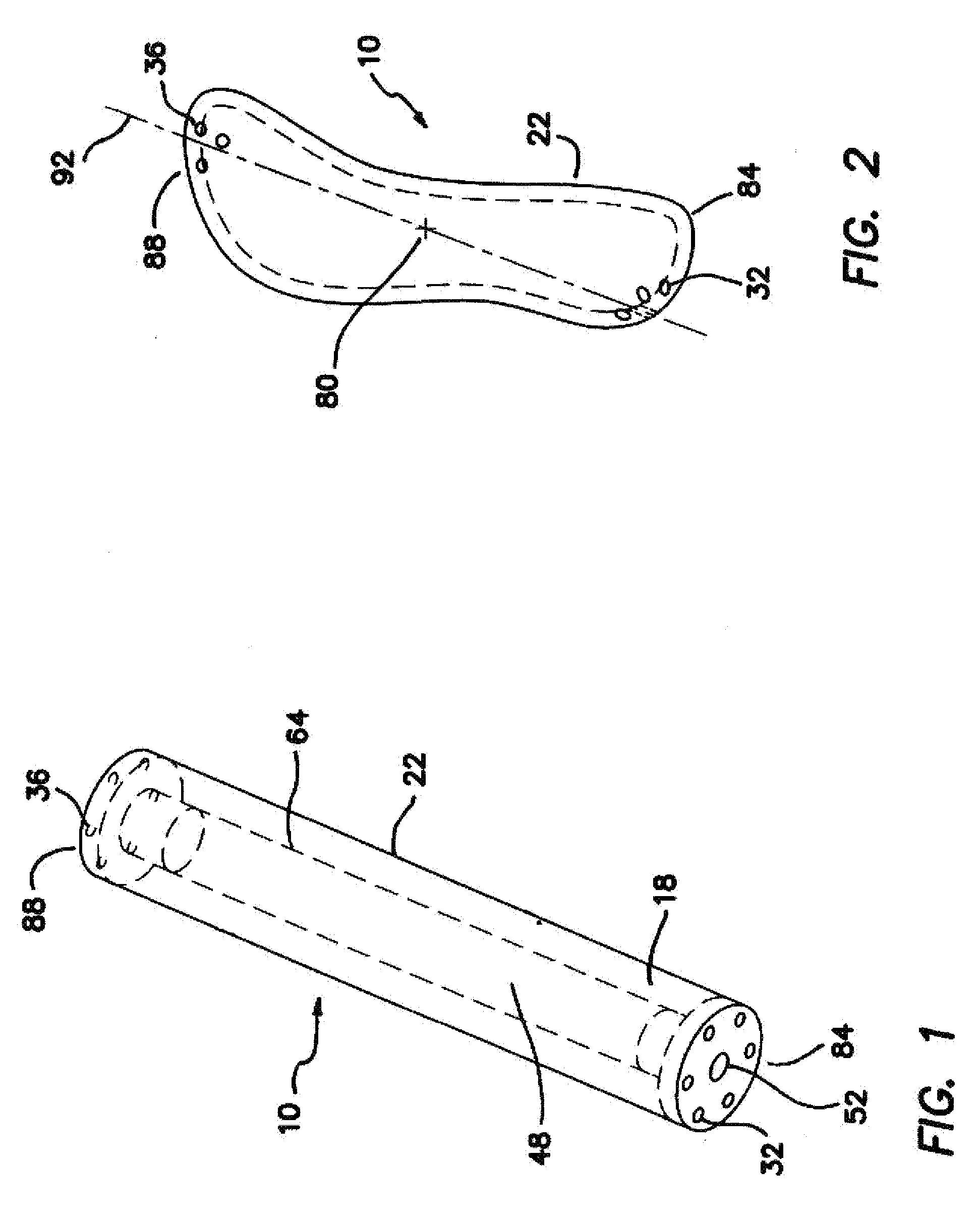
[0039]One embodiment of the present invention provides a means of construction, deployment, and rigidization of inflatable annular cross-sectional structural booms. Referring now to FIG. 1, which is a perspective view of a boom structure. In this embodiment, the structure is shown to substantially circular exterior cross-section. The structure is further provided with an outer wall 22, an inner wall 64, at least one exhaust port 36, and a plurality of openings 32. Although six such openings 32 are depicted, a different number could also be used. These openings 32 are arranged on a first end 84 of the boom structure 10. The exhaust ports 36 are on a second end 88. Generally, they will be equally spaced around a central axis. The openings 32 are configured to allow for the introduction of rigidizable fluid into the structure 10. The structure 10 may further include an inflatable bladder 48. When present, the bladder 48 is attached to the containment member 18 and has at least one pres...


PUM


Abstract

An inflatable and rigidizable structure for use as a habitat or a load bearing structure is disclosed. The structure consists of an outer wall and an inner wall defining a containment member and a bladder. The bladder is pressurized to erect the structure from an initially collapsed state. The containment member is subsequently injected with rigidizable fluid through an arrangement of injection ports. Exhaust gases from the curing rigidizable fluid are vented through an arrangement of exhaust ports. The rate of erection can be controlled by frictional engagement with a container or by using a tether. A method for fabricating a tubular structure is disclosed.

Description

STATEMENT OF GOVERNMENT INTEREST[0001]This invention was made in part by employees of the United States Government and may be manufactured and used by or for the Government of the United States of America for government purposes without payment of any royalties thereon or therefore.FIELD OF INVENTION[0002]The invention pertains to inflatable, rigidizable, and deployable structures. More particularly, the invention relates to load bearing structures or habitation structures adapted for use in terrestrial and extraterrestrial environments.BACKGROUND OF THE INVENTION[0003]Many civil and aerospace engineering structures are designed for ease of transport and storage, weight and financial economy. For these reasons, a number of inflatable and rigidizable structures have been developed. One problem which has not been fully addressed is the issue of providing uniform rigidization throughout the structure, particularly when larger structures or assembled structures are constructed. Some rel...

Claims


Application Information

Patent Timeline
IPC IPC(8): E04G11/04E04B1/35
CPCB64G1/222B64G2001/224E04B1/166E04G11/04E04B1/3211E04B2001/1939E04B2001/3258E04B1/169E04G11/045B64G1/2227B64G1/2222
Inventor TINKER, MICHAEL L.SCHNELL, ANDREW R.
Owner NASA
Learn More