
Control Method and Control Device for Engine

a control device and engine technology, applied in the direction of electric control, machines/engines, mechanical equipment, etc., can solve the problems of deteriorating precision of engine torque control, and achieve the effect of accurately and efficiently correcting the efficiency of torque generation and high-precise engine torque control

Inactive Publication Date: 2009-01-15
HITACHI LTD
View PDF2 Cites 46 Cited by
  • Summary
  • Abstract
  • Description
  • Claims
  • Application Information

AI Technical Summary

Benefits of technology

[0007]The present invention is to solve the above-described problems, and an object of the invention is to provide high-precise engine torque control means by efficiently correcting torque generation efficiency with respect to an ignition retard amount.
[0009]According to the invention, it is possible to realize the high-precise engine torque control means by accurately and efficiently correcting the torque generation efficiency with respect to the ignition retard.

Problems solved by technology

Accordingly, when the ignition retard control is carried out by using a single ignition timing efficiency table, a problem arises in that precision of the engine torque control deteriorates because it is not possible to cope with a variation in ignition timing efficiency.

Method used


Image

  • Control Method and Control Device for Engine
  • Control Method and Control Device for Engine
  • Control Method and Control Device for Engine

Examples


embodiment 1

[0044]Next, Embodiment 1 according to the invention applied to the torque base-type engine control will be described with reference to FIGS. 6 to 8. FIG. 6 shows the ignition retard amount calculating unit 229 which calculates a desired ignition retard amount 230 on the basis of the input ignition retard torque correction rate 228. The ignition retard amount calculating unit 229 includes an ignition timing reference efficiency calculating unit 301 and an ignition timing efficiency correcting unit 302 which corrects the ignition timing efficiency.

[0045]As shown in FIG. 7, the ignition timing reference efficiency calculating unit 301 formulates a reference relationship between the ignition retard amount and the torque generation efficiency as a quadratic function “Y=a0X2+b0X+C0”. In addition, the quadratic function is not fixed, and the respective coefficients thereof are corrected when an ignition timing correction amount calculating unit 305 requests a correction. The correction is ...

embodiment 2

[0052]In Embodiment 2, the ignition timing efficiency and the combustion duration use the classical multidimensional table and map. The number of processes is not appropriate, but the calculation algorithm is stable.

embodiment 3

[0053]Next, the contents of the combustion duration calculating unit 303 related to Embodiment 3 will be described with reference to FIG. 11. In this Embodiment, the combustion duration is calculated by using a combustion duration theoretical equation 403 as a theoretical equation for calculating the combustion duration, and a turbulence combustion speed ST as a main parameter is expressed by the following equation.

ST=(1+u)SL   (2)

u=f(Ne, ,)   (3)

SL=f(Φ, EGR, T, P, ,)   (4)

[0054]At this time, u: turbulence intensity, SL: laminar burning speed (velocity), Ne: engine rpm, Φ: equivalent ratio, EGR: exhaust gas remaining ratio, T: cylinder temperature, and P: pressure in the cylinder.

[0055]Combustion duration COMB_CA is expressed by the following equation:

COMB—CA=COMB—CA0×(ST0 / ST)   (5)

[0056]wherein the combustion duration corresponding to the ignition timing reference efficiency curve is denoted by COMB_CA0 and the turbulence combustion speed at that time is denoted by ST0.

[0057]The th...


PUM


Abstract

In a control method and control device for an engine, in order to prevent torque control precision from deteriorating while performing an ignition retard control in a variable valve engine, when a torque down control is carried out by using the ignition retard, combustion duration is calculated in consideration of valve timing or an engine rpm for each driving state, and a characteristic of a reference ignition timing efficiency curve is corrected on the basis of a difference between the combustion duration and a combustion duration reference value which is set in advance.

Description

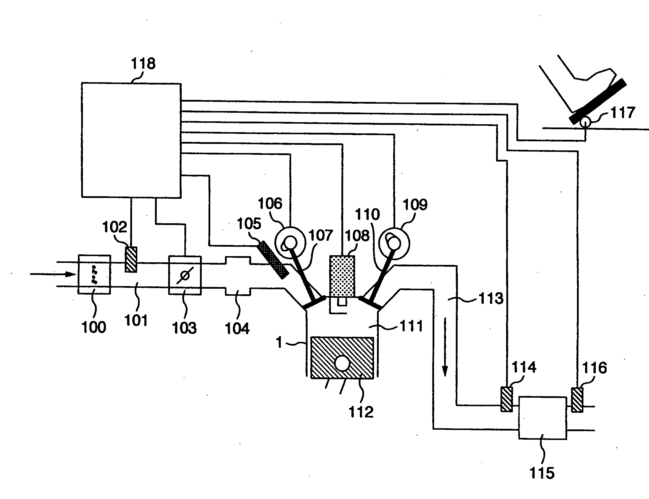
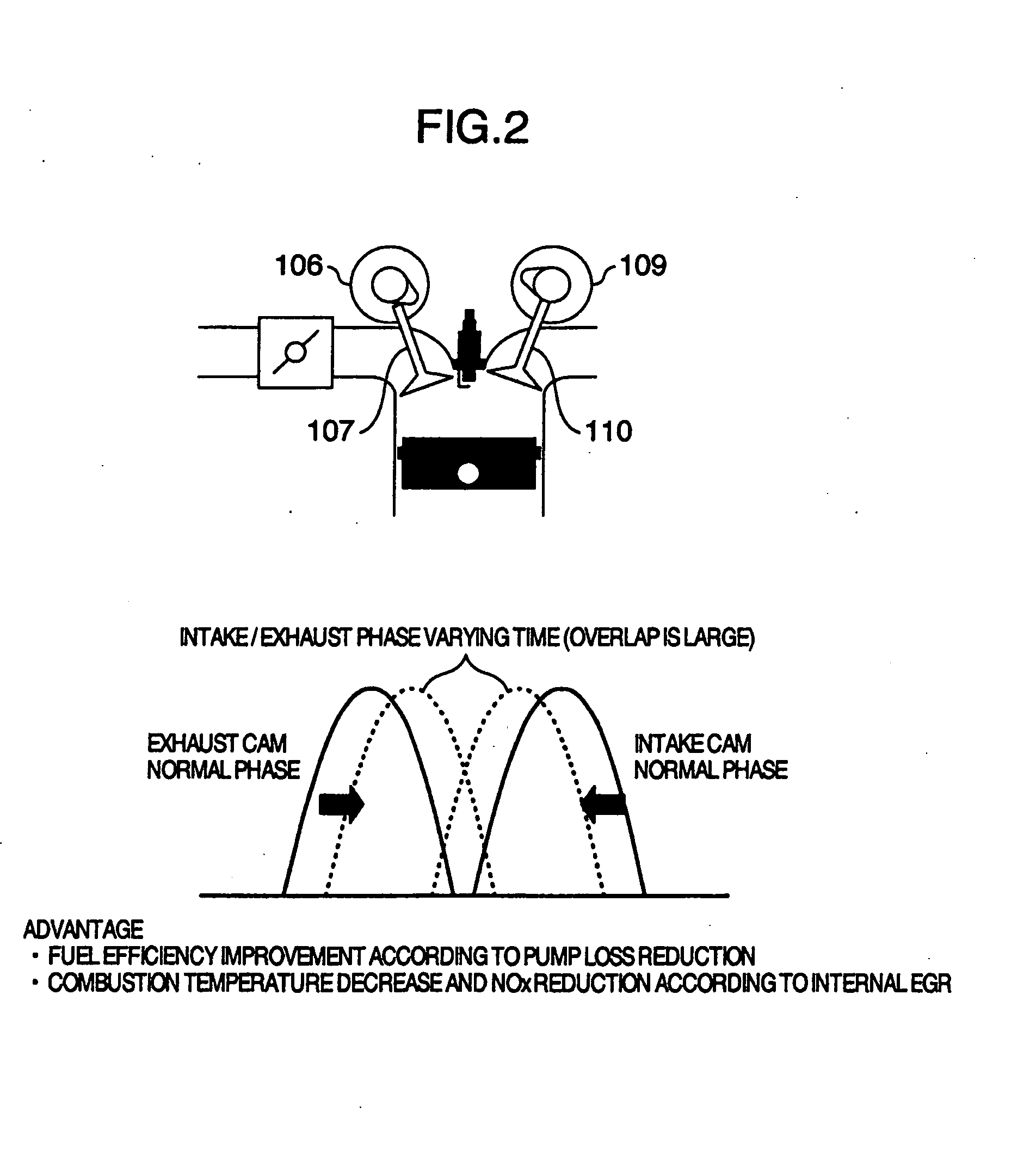
FIELD OF THE INVENTION[0001]The present invention relates to a control device for an engine mounted to a vehicle.DESCRIPTION OF RELATED ART[0002]A variable valve system has been noted for a technique concerned with a gasoline engine for a vehicle. The variable valve system variably controls valve timing or valve-lift amount in accordance with a driving state. Specifically, the variable valve system varies the valve timing or the valve-lift amount in accordance with the driving state by providing a hydraulic or electric actuator at a position around a cam shaft fixed portion of an engine. The variable valve system is advantageous in that fuel efficiency is improved by reducing a pump loss or exhaust gas such as HC or NOx is reduced by adjusting a valve overlap.[0003]Meanwhile, a high-response torque down control using an ignition retard is known as another technique concerned with the gasoline engine for the vehicle. The high-response torque down control using the ignition retard ind...

Claims


Application Information

Patent Timeline
IPC IPC(8): F16H59/74
CPCF02D35/02F02D41/0025F02D41/0087F02D41/1497Y10T477/67F02D2041/001F02D2250/18F02P5/153Y02T10/46F02D2011/102Y02T10/40
Inventor SATOU, SHINYASUZUKI, KUNIHIKONEMOTO, MAMORU
Owner HITACHI LTD
Learn More