Light receiving optical system, and spectrophotometer incorporated with the same

a technology of optical system and spectrophotometer, which is applied in the direction of optical radiation measurement, instruments, spectrometry/spectrophotometry/monochromator, etc., can solve the problems of impairing measurement reproducibility and affecting measurement reproducibility, and achieve the effect of increasing the amount of incident ligh

Inactive Publication Date: 2009-01-15
KONICA MINOLTA SENSING INC
View PDF2 Cites 3 Cited by
  • Summary
  • Abstract
  • Description
  • Claims
  • Application Information

AI Technical Summary

Benefits of technology

[0014]The inventive light receiving optical system and the inventive spectrophotometer are advantageous in increasing the incident light amount at a small view angle, in other words, control the incident light amount depending on a switching operation of the view angle, with no or less influence of reproduction error resulting from movement of an optical system for view angle switching control.

Problems solved by technology

This may displace the exit position of exit light 903c through the exit end 904b, thereby impairing measurement reproducibility.
As a result, the diffraction efficiency i.e. the reflection efficiency of the concave diffraction grating is changed, which may impair measurement reproducibility.

Method used


Image

  • Light receiving optical system, and spectrophotometer incorporated with the same
  • Light receiving optical system, and spectrophotometer incorporated with the same
  • Light receiving optical system, and spectrophotometer incorporated with the same

Examples


first modification

[0034](First Modification)

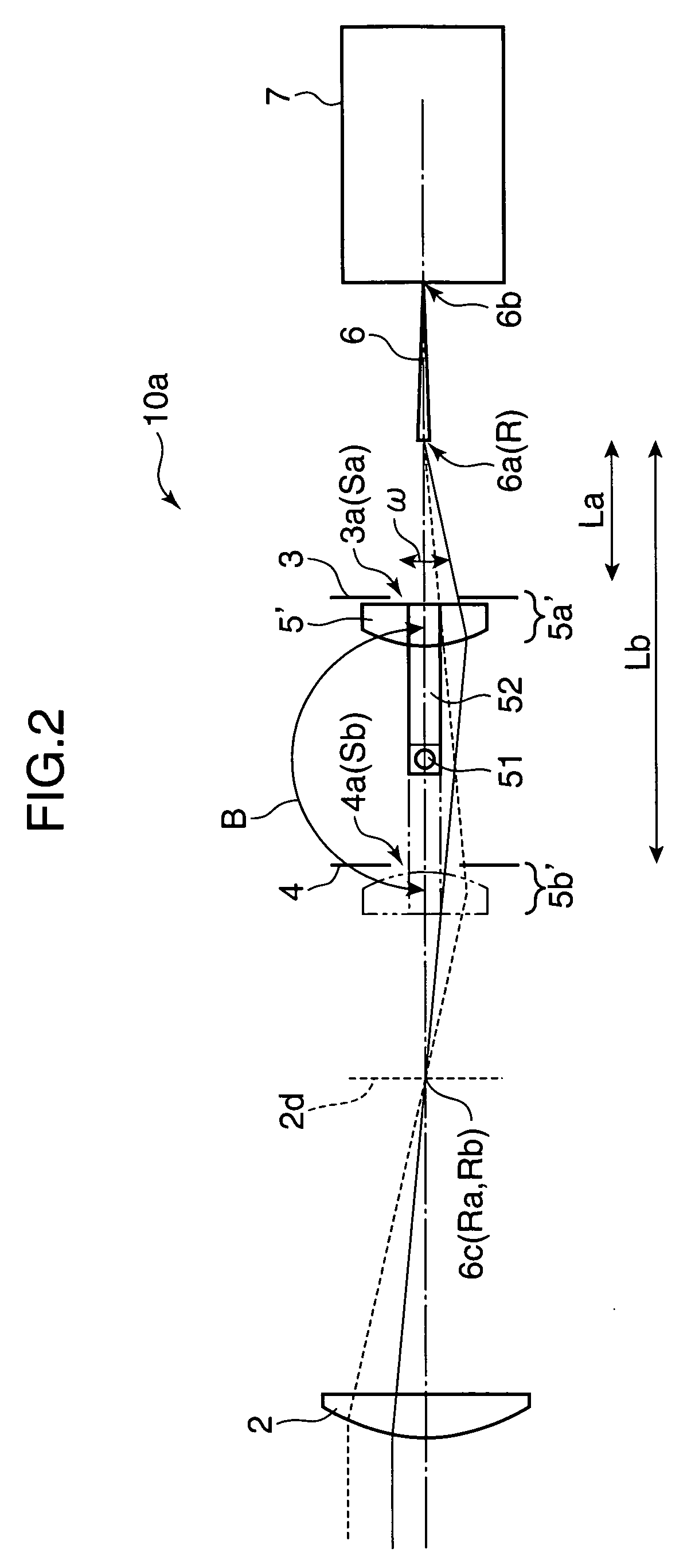
[0035]As described above, the light receiving optical system 10 provided with the relay lens 5 as a relay optical system may be configured into a light receiving optical system 10a as shown in FIG. 2. Specifically, the light receiving optical system 10a may include: a relay lens 5′, as a flat convex lens, having an incident plane and an exit plane of curvatures asymmetrical to each other, e.g. having one plane thereof shaped into a flat plane and the other plane thereof shaped into a convex plane, in place of the relay lens 5 as a biconvex lens; and a mechanism constructed in such a manner that one end of an arm unit 52 is aligned with an axis of a rod 51 about which the arm unit 52 is pivotally rotated, and the other end of the arm unit 52 is attached to the relay lens 5′, whereby the relay lens 5′ is selectively switched between a first conjugated position 5a′ and a second conjugated position 5b′ by a manual operation or a predetermined driver. The arm un...

second modification

[0037](Second Modification)

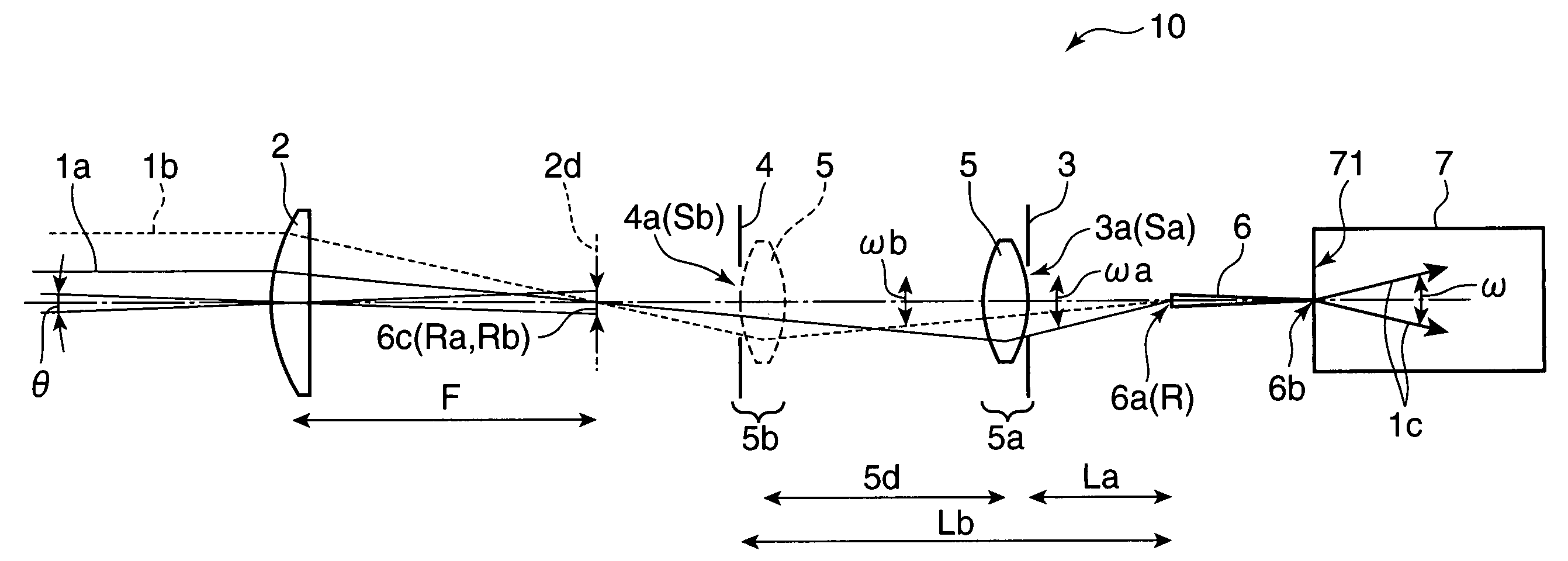
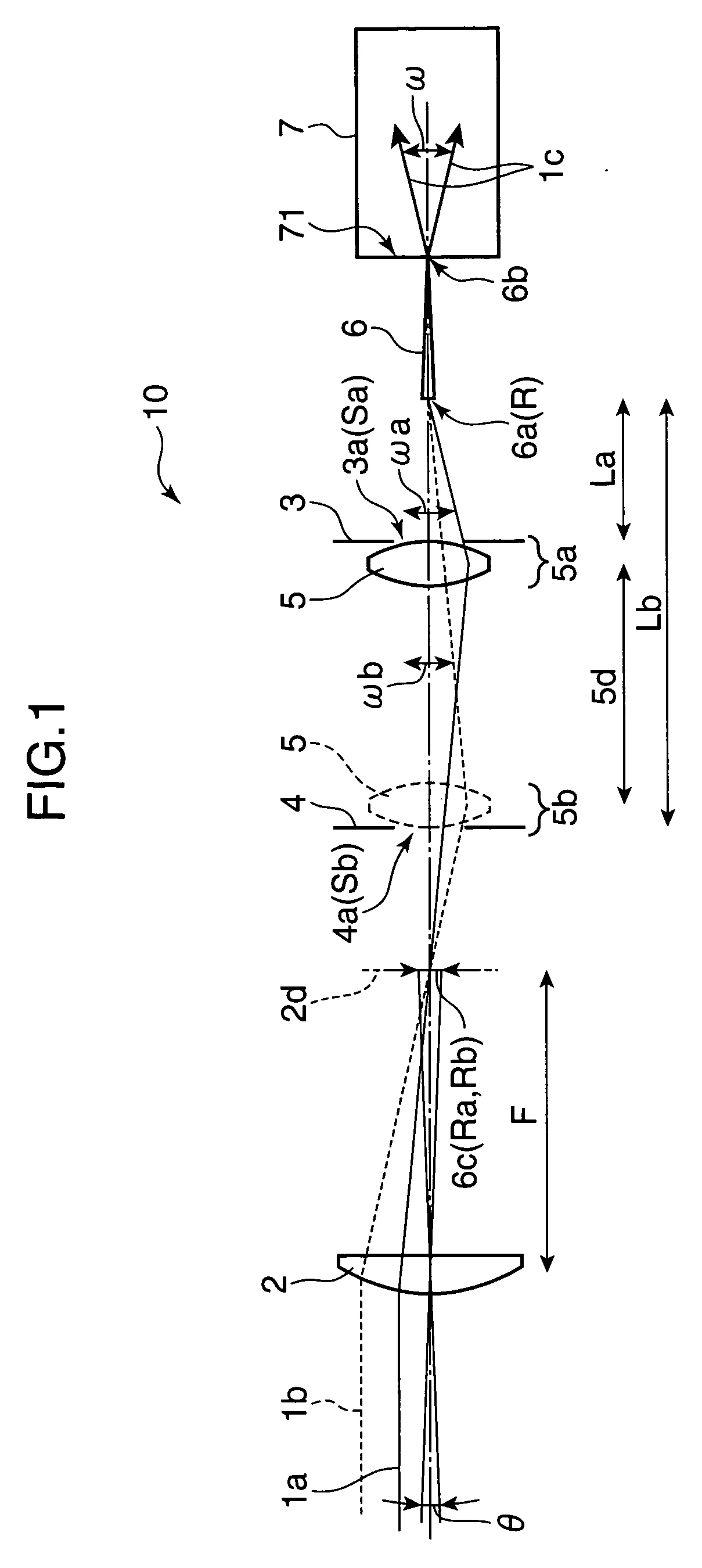
[0038]As described above, in the light receiving optical system 10 shown in FIG. 1, a light flux from a measurement area as a measurement site is convergently incident onto the incident end 6a of the conversion fiber 6. However, in view of a point that an image in the periphery of the measurement area is formed on a perimeter of the incident end 6a as an incident end surface, the light receiving optical system 10 for view angle switching control in the embodiment may be used in combination with a viewfinder optical system for viewing the measurement area. In the modification, as shown in FIG. 3, for instance, the viewfinder optical system e.g. an electronic viewfinder system may include a flat mirror 82 formed with an opening 81 in the middle thereof, and an image pickup system 80 comprised of an image pickup lens 83 and an image sensor 84. The plane mirror 82 is tiltingly mounted on a conversion fiber 6 at a predetermined angle with respect to the optical...


PUM

PropertyMeasurementUnit
view angleaaaaaaaaaa
wavelengthaaaaaaaaaa

Abstract

A light receiving optical system includes: a relay optical system for converging light to be measured which has been converged on an image plane of an objective optical system on a view angle defining aperture for incidence through the view angle defining aperture. The light receiving optical system has the relay optical system with a relay lens operable to be selectively switched between a first and a second conjugated positions, and a first and a second light flux limiting aperture members disposed in proximity to the relay lens in the case where the relay lens is selectively switched between the first and the second conjugated positions. The relay optical system selectively forms, on the image plane of the objective optical system, an enlarged image and a reduced image of the view angle defining aperture in the case where the relay lens is selectively switched between the first and the second conjugated positions to define an incident light flux through the view angle defining aperture by a first and a second light flux limiting apertures, respectively, in the case where the relay lens is selectively switched between the first and the second conjugated positions. A spectrophotometer has the light receiving optical system.

Description

[0001]This application is based on Japanese Patent Application No. 2007-183555 filed on Jul. 12, 2007, the contents of which are hereby incorporated by reference.BACKGROUND OF THE INVENTION[0002]1. Field of the Invention[0003]The present invention relates to a light receiving optical system to be incorporated in a spectral device such as a spectrophotometer, and more particularly to a light receiving optical system operable to switch a view angle, and a spectrophotometer incorporated with the light receiving optical system.[0004]2. Description of the Related Art[0005]FIG. 7 is a diagram showing an example of a conventional light receiving optical system to be incorporated in a spectral device such as a spectrophotometer. The light receiving optical system 900 shown in FIG. 7 has an aperture plate (hereinafter, called as a “view angle switching aperture plate”) 902 for view angle switching control. The view angle switching aperture plate 902 is formed with an aperture 902a having a r...

Claims


Application Information

Patent Timeline
Patent Type & Authority Applications(United States)
IPC IPC(8): G01N21/00G01J3/42
CPCG01J3/02G01J3/0208G01J3/0218G01J3/0237G02B26/0816G01J3/0289G01J3/04G02B23/24G01J3/024
Inventor IMURA, KENJI
Owner KONICA MINOLTA SENSING INC
Why Eureka
Try Eureka