
Count uniformity correction in flux space for pixilated semiconducting radiation detectors

a detector and flux space technology, applied in the field of photon detection systems, can solve problems such as non-uniform pixel response, non-uniform pixel response due to material sensitivity, and non-linear loss in measured counts

Active Publication Date: 2009-01-15
PRODUCE
View PDF5 Cites 1 Cited by
  • Summary
  • Abstract
  • Description
  • Claims
  • Application Information

AI Technical Summary

Problems solved by technology

However, the material upon which such systems are based has crystal defect densities that are spatially non-uniform, thereby producing a non-uniform pixel response (sensitivity).
At high flux densities, the non-uniform pixel response due to material sensitivity is made worse by a non-linear loss in measured counts due to the response of readout electronics.
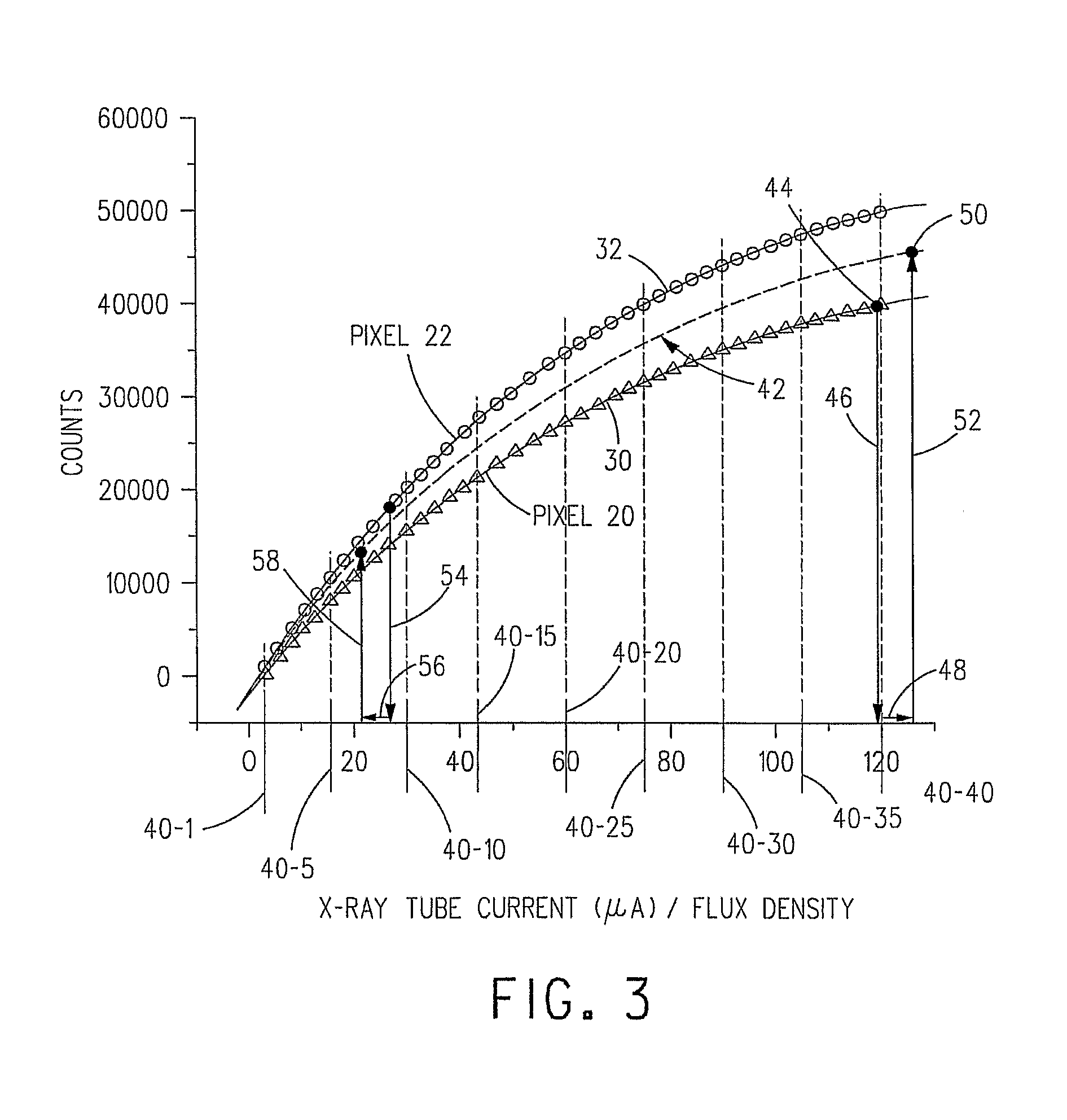
Namely, simply elevate (or suppress) a pixel's counts to some averaged level using a constant multiplier. FIG. 4, however, demonstrates that for higher fluxes this dependence is, in fact, quite nonlinear.
However, these correction schemes fail away from the flux density where the correction was made.

Method used


Image

  • Count uniformity correction in flux space for pixilated semiconducting radiation detectors
  • Count uniformity correction in flux space for pixilated semiconducting radiation detectors
  • Count uniformity correction in flux space for pixilated semiconducting radiation detectors

Examples


Embodiment Construction

[0032]The present invention will be described with reference to the accompanying figures where like reference numbers correspond to like elements.

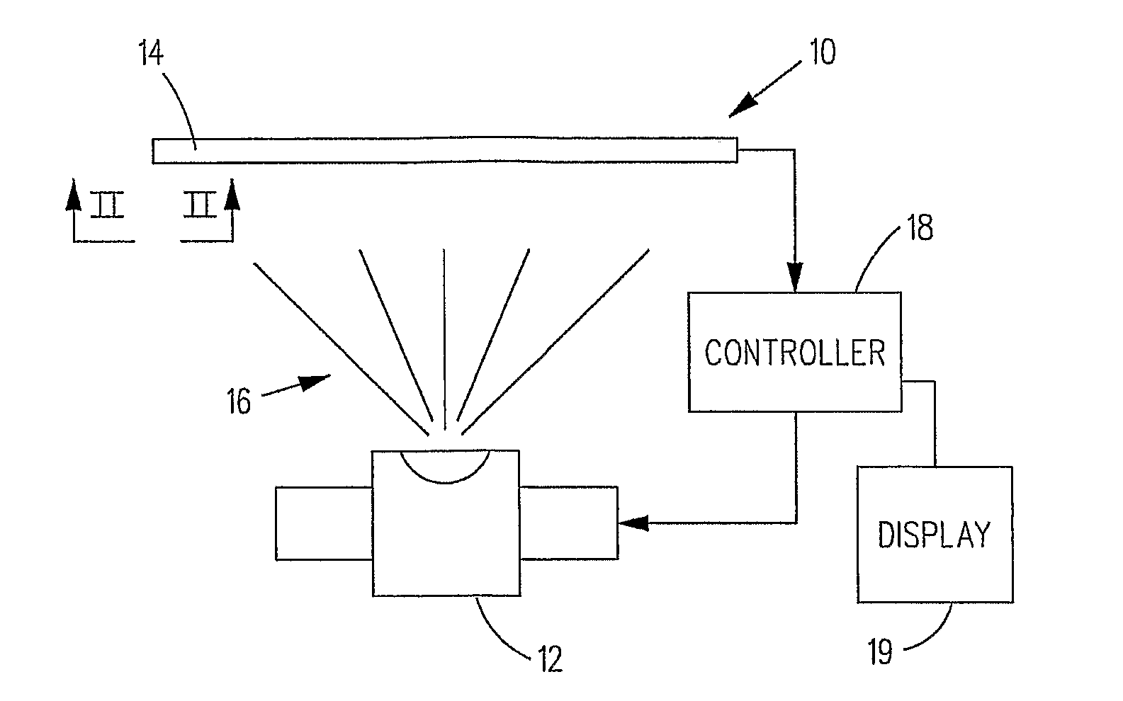
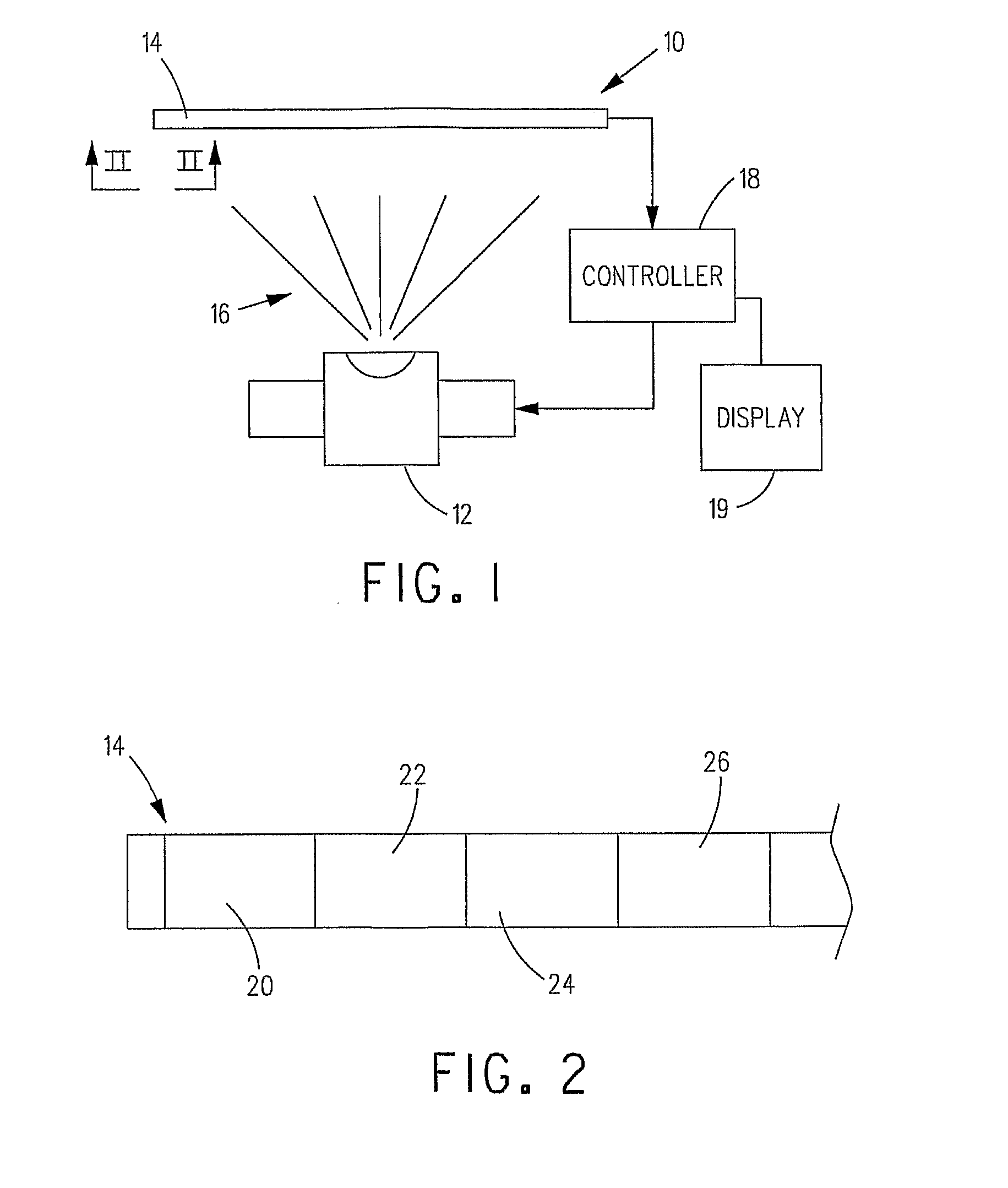
[0033]With reference to FIG. 1, a radiographic imaging system 10 includes a high energy photon source 12, such as, without limitation, an x-ray source or a gamma ray source, and at least one detector array 14 positioned in a transmission path 16 of photons output by photon source 12. If desired, a collimator (not shown) may be positioned between photon source 12 and detector array 14 for shaping, focusing and restricting the photons that impinge on detector array 14.

[0034]One or more controllers 18 can be provided and operative for controlling the operation of photon source 12 and for detecting and processing photon events detected by the radiation detection elements or pixels (described hereinafter) of detector array 14. The depiction in FIG. 1 of a single controller 18 coupled to photon source 12 and detector array 14 is not to be constr...


PUM


Abstract

In operation of a photon counting detecting system (10), a number of pulse counts output by least one pixel (20) of a photon counting detector in response to experiencing a photon flux density during a sample interval is acquired and a photon flux density (46) or value related thereto corresponding to the pulse counts output by the pixel (20) is determined. A correction (48) for the thus determined photon flux density (46) or value related thereto is determined. A corrected number of pulse counts (52) is determined for the pixel (20) as a function of the thus determined corrected photon flux density value or value related thereto. An image can be displayed that is a function of the corrected number of pulse counts for pixels of the system.

Description

BACKGROUND OF THE INVENTION[0001]1. Field of the Invention[0002]The present invention relates to photon detection systems and, more particularly, to correcting the pulse counts output by multi-pixel photon counting detectors of such systems.[0003]2. Description of Related Art[0004]Applications that utilize gamma or x-ray cameras, gages or imaging systems based on pixilated semiconducting radiation detectors require the use of measured counts per pixel in a given period of time to accurately discern the incident photon flux density. Most imaging applications rely on a collective uniform response of the pixels of the system when subjected to a uniform incident photon flux density. However, the material upon which such systems are based has crystal defect densities that are spatially non-uniform, thereby producing a non-uniform pixel response (sensitivity). At high flux densities, the non-uniform pixel response due to material sensitivity is made worse by a non-linear loss in measured ...

Claims


Application Information

Patent Timeline
Patent Type & Authority Applications(United States)
IPC IPC(8): G01T1/24
CPCH04N5/32H04N5/367H04N5/365H04N25/30H04N25/773H04N25/67H04N25/68
Inventor BALE, DEREK S.
Owner PRODUCE
Learn More