Internal valve and methods of use for inflatable objects
- Summary
- Abstract
- Description
- Claims
- Application Information
AI Technical Summary
Benefits of technology
Problems solved by technology
Method used
Image
Examples
Embodiment Construction
—PREFERRED EMBODIMENTS—FIGS. 1-3
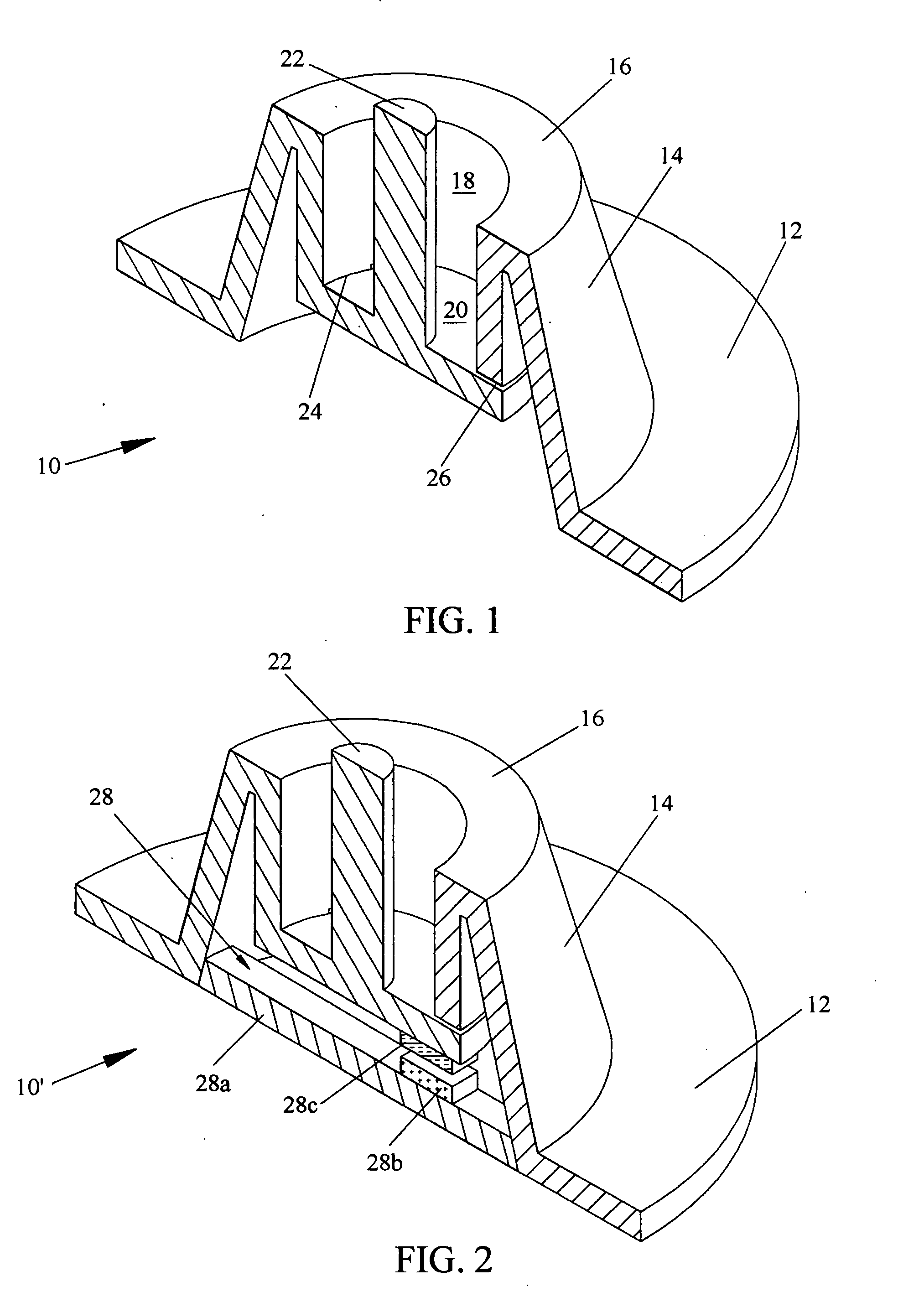
[0031]A preferred embodiment of the internal valve of the present invention is illustrated in FIG. 1. An internal valve 10 comprises an annular valve seat 12, a conical wall or diaphragm 14, an annular connection 16, a tube or tubular member 18, a check flap 20 and a discharging cylinder or finger 22. Wall 14 extends upwardly from seat 12 and connects with the top of tube 18 through connection 16. The body of the tube extends downwardly. The flap is connected with the bottom of the tube partially by a hinge 24 and functions as a check valve. The flap is preferably formed from the bottom wall of tube 18 that is partially severed from the body by a shearing cut 26, as known in the art. One end of finger 22 is secured substantially to the center of flap 20 inside the tube and the other end is extended above the top surface of connection 16 outside the tube. Therefore, the flap moves to an open position if finger 26 is pushed down. Valve 10 is preferably ...
PUM
 Abstract
Description
Claims
Application Information
 - R&D
- Intellectual Property
- Life Sciences
- Materials
- Tech Scout
- Unparalleled Data Quality
- Higher Quality Content
- 60% Fewer Hallucinations
Browse by: Latest US Patents, China's latest patents, Technical Efficacy Thesaurus, Application Domain, Technology Topic, Popular Technical Reports.
© 2025 PatSnap. All rights reserved.Legal|Privacy policy|Modern Slavery Act Transparency Statement|Sitemap|About US| Contact US: help@patsnap.com


