
Sport goggle with side vent for improved ventilation

a technology of ventilation and goggles, applied in the field of improved goggles, can solve the problems of fogging or condensation on the window, lack of low pressure system for removing air from the face cavity, and fogging of the goggles, so as to achieve the effect of not easily clogged by snow and easy cleaning

Inactive Publication Date: 2007-02-27
K 2 CORP
View PDF35 Cites 30 Cited by
  • Summary
  • Abstract
  • Description
  • Claims
  • Application Information

AI Technical Summary

Benefits of technology

"The invention is an improved goggle for sports and activities where non-fogging goggles are preferred or required. The goggle features one or more intake apertures on the lens and body of the goggle that communicate air to the eye chamber. These intake apertures are positioned in the front face of the goggle when worn and can be in multiple points on the front. The goggle also has side exhaust apertures to vent air from the eye chamber. An optional moisture trap or dust filter can be used to prevent moisture or dust from entering the eye chamber. The goggle uses shaped edges to create low pressure zones to draw air from the eye chamber. The invention also includes air directional components that are not easily clogged and can be easily cleaned. Overall, the invention provides improved air flow and pressure in the eye chamber for better protection and performance."

Problems solved by technology

In cold climates and in freezing venues such as ski slopes and high altitudes an inherent problem encountering goggle wearing individuals is that of fogging of the goggle lens.
The face of the user radiates heat and tends to heat the air inside the goggle cavity behind the lens much like the windshield of a car tends to fog when the air inside the car is warmer than the air outside the car, thus causing fog or condensation on the window.
Tackles also lacks a low pressure system to pull air from the face cavity.
U.S. Pat. No. 5,652,965 (Crooks) teaches a non-fogging goggle, but Crooks also uses an elongated slot formed in the mask portion below the lens that is easily clogged and also lacks negative pressure venting.
However, Harris lacks any positive pressure or negative pressure to aid in the flow.
U.S. Pat. No. 4,290,673 (Yamamoto) discloses ski goggles which have a heating means to heat the space between two lenses but lacks any pressurized low pressure evacuation of air from the internal cavity.

Method used


Image

  • Sport goggle with side vent for improved ventilation
  • Sport goggle with side vent for improved ventilation
  • Sport goggle with side vent for improved ventilation

Examples


Embodiment Construction

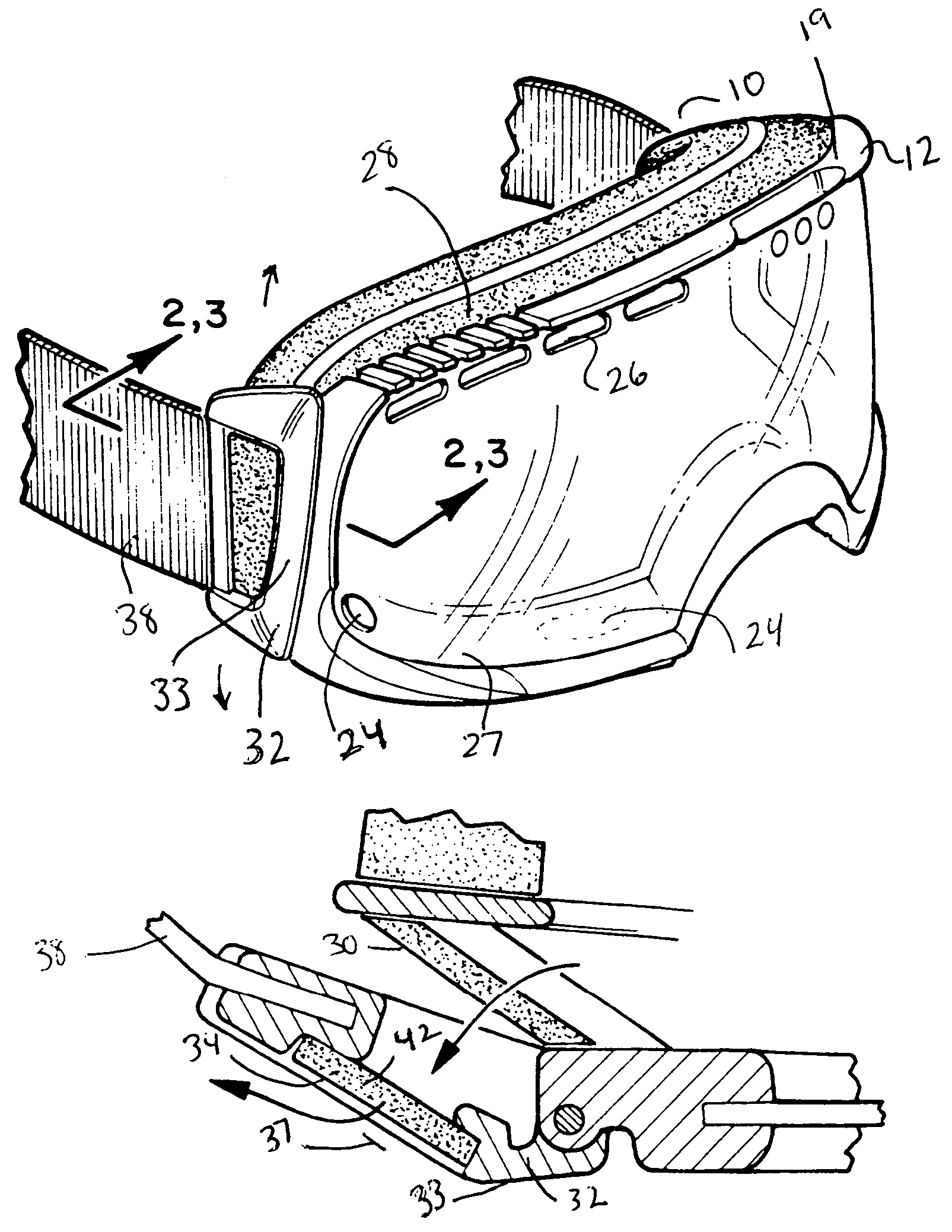
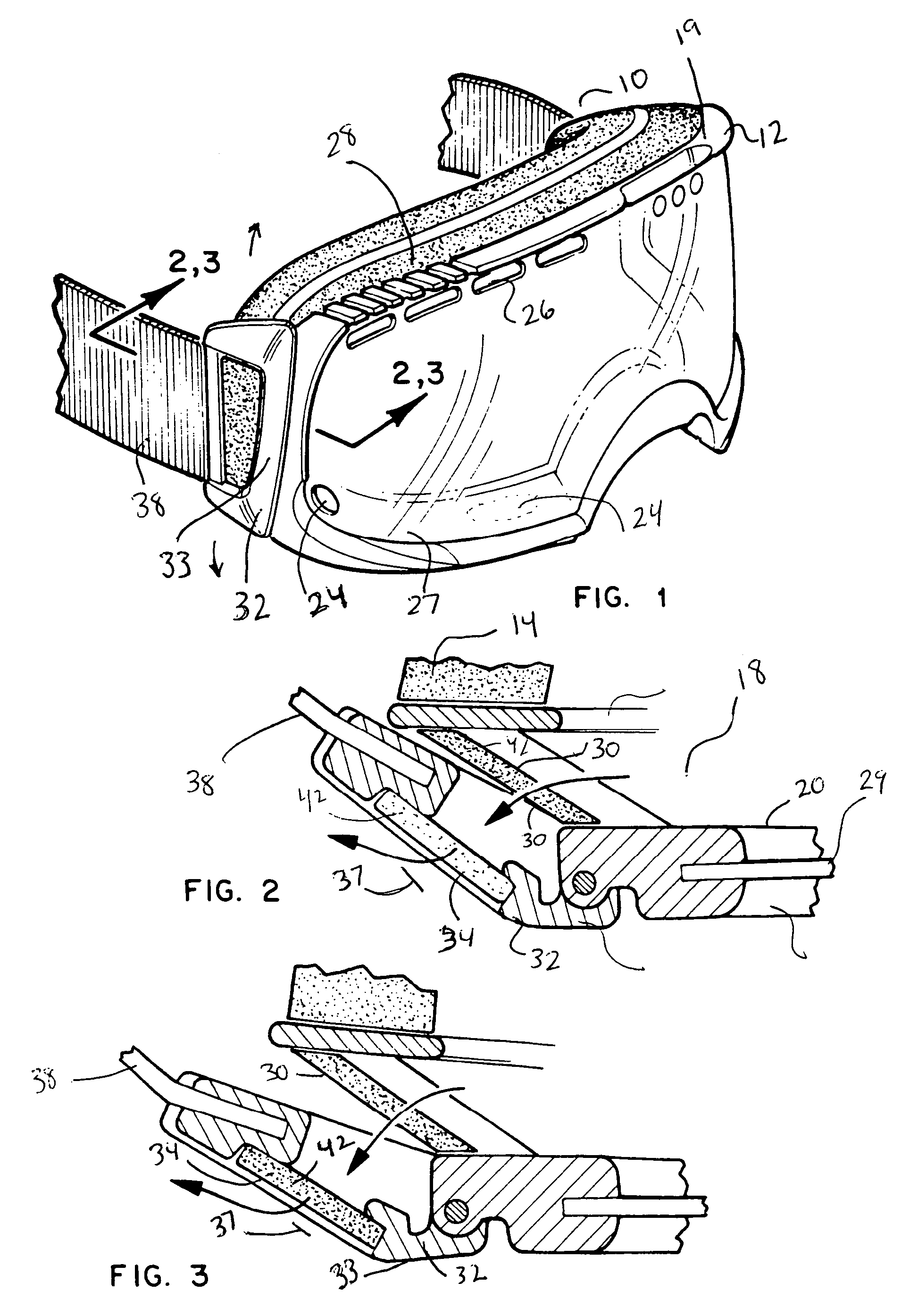
[0031]Referring now to the drawings FIG. 1–4 wherein similar parts of the invention are identified by like reference numerals, the figures disclose the improved sport goggle 10 featuring improved air extraction using directed aerodynamic airflow. The goggle body 12 is shaped to conform to a human face on the inside surface 14 which is conventionally covered in foam or similar soft material. The goggle lens 16 is operatively mounted in the body 12 and conventionally is best curved around the face of the user to provide side viewing. In use as worn on a user, an eye cavity 18 is formed and best defined by the area between the user's face, the inside surface 20 of lens 16, the top wall 19, the sidewalls 21, and the bottom wall or ledge 27.

[0032]The lens 16 in the current best mode of the device 10 would be a unitary lens featuring two lenses separated by an insulating space 29 to help therebetween to reduce fogging, although the disclosed air evacuation system herein will also enhance ...


PUM


Abstract

An improved sport goggle for skiing, motorcycling, paintball, racing, and other sports featuring clip-mounted side apertures communicating with the eye cavity of the goggle through adjacent venting apertures. Venting of the eye cavity of the sport goggle is aided by forming of the clip shape to create low pressure zones adjacent to the side venting apertures. The clips are rotationally attached to the goggle to provide an adjustable mount for the strap around heads or helmets while still forming the negative air pressure zone in all rotated positions. The clips may also be provided in a kit of differently dimensioned clips to adjust the negative air pressure venting characteristics of the clips and goggle to the intended sport or task.

Description

BACKGROUND OF THE INVENTION[0001]1. Field of the Invention[0002]The present invention relates to an improved goggle for sports and other activities where eye protection and improved vision are desirable. More particularly it relates to a goggle which incorporates a system of high and low pressure areas external to the goggle to increase ventilation of the enclosed eye cavity to prevent fogging of the goggle lens. The disclosed device additionally features increased ventilation from side vents which communicate through a clip also used for strap attachment. This clip is rotationally engaged with the body of the goggle and allows for attachment of the head strap to the goggle on one side of the clip with the opposite side rotationally engaged to the body of the goggle. This rotational attachment may be by hinge, flexible flap in an extension, or other means of attachment to allow for the rear end of the clip to rotate away from the goggle body.[0003]An aperture formed in the clip betw...

Claims


Application Information

Patent Timeline
Patent Type & Authority Patents(United States)
IPC IPC(8): A61F9/02
CPCA61F9/027
Inventor HUSSEY, PATRICK P.
Owner K 2 CORP
Learn More