
Transmission Belt

a transmission belt and belt body technology, applied in the field of transmission belts, can solve the problems of cracks, transmission belts to be heated to a higher temperature than ever, tight packing of parts, etc., and achieve the effects of suppressing deterioration, reducing hysteresis loss, and high modulus

Inactive Publication Date: 2009-01-08
BANDO CHEM IND LTD
View PDF3 Cites 22 Cited by
  • Summary
  • Abstract
  • Description
  • Claims
  • Application Information

AI Technical Summary

Benefits of technology

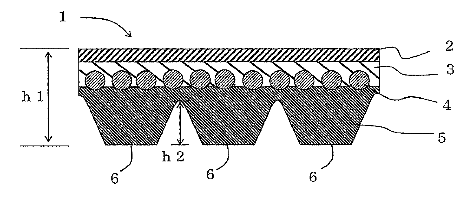
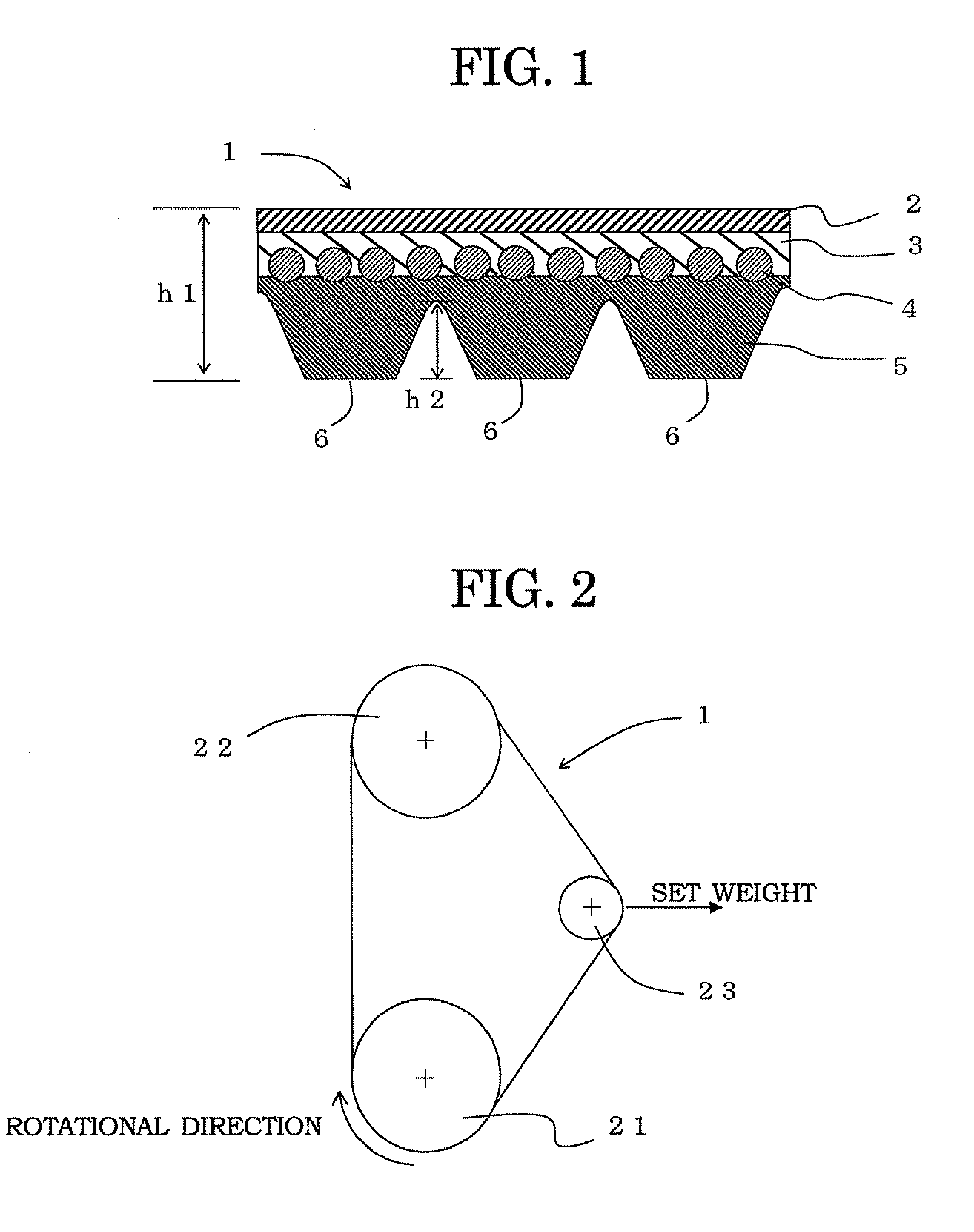
[0039]According to the present invention, the rubber layer to be adhered to the core wires is formed to have a durometer hardness (shore A) of not less than 72 and not more than 85, or have a tensile stress of not less than 0.5 MPa and not more than 1.7 MPa when stretched 10% in the belt longitudinal direction at 25° C., it is possible to reduce hysteresis loss or the like as compared with the case in which the rubber layer to be adhered to the core wires has a high modulus, and suppress deterioration of the transmission efficiency.
[0040]In addition, since the rubber layer to be adhered to the core wires has ethylene-α-olefin elastomer used as the base rubber, it is possible to improve heat resistance and cold resistance of the rubber layer itself and hence improve durability of the transmission belt.
[0041]Furthermore, since the rubber layer adhered to the core wires is formed to have a durometer hardness (shore A) of not less than 72 and not more than 85, or have a tensile stress of not less than 0.5 MPa and not more than 1.7 MPa when stretched 10% in the belt longitudinal direction at 25° C., and the rubber layer is formed to have a weight increase of 90% or less after immersed in light oil for 48 hours at 25° C. or have a weight increase of 80% or less after immersed in toluene for 48 hours at 25° C., it is possible to reduce dynamic heat build-up during belt running, and hence reduce separation or pop-out.
[0042]That is, it is possible to reduce deterioration of the transmission efficiency of a transmission belt while at the same time improve the durability.
[0043]The fact that this rubber layer is formed to have a weight increase of 90% or less after immersed in light oil for 48 hours at 25° C. or have a weight increase of 80% or less after immersed in toluene at 25° C. can be confirmed by taking out the rubber layer adhered to the core wires from the transmission belt, then removing the core wires, then immersing this in light oil or toluene of such an amount as to satisfactorily swell the rubber layer, and then measuring the weight change before and after immersion.
[0044]For example, the initial weight (M0) before immersion can be determined by taking out a small piece of rubber having a thickness of about 0.1 mm from the transmission belt to have about 50 mg in total, and then weighing it by an electronic balance having a minimum measuring unit of about 0.1 mg.

Problems solved by technology

Furthermore, the reduction in size of the system or device causes heating parts to be tightly packed in the system or device, which in turn causes the transmission belt to be heated to a temperature higher than ever.
Therefore, cracks may take place in an adhesive interface between a compression rubber layer and an adhesive rubber layer, or between core wires and these rubber layers in a transmission belt having a rubber layer made of ethylene-α-olefin elastomer.
Therefore, cracks or the like are likely to take place in an adhesive interface between a compression rubber layer and an adhesive rubber layer, or between core wires and these rubber layers.
However, when core wires are adhered to a rubber layer having a high modulus in the manner as proposed in those Patent Documents, the rubber layer having a high modulus to be adhered to core wires itself may cause cracks therein.
Also, when the adhesive rubber layer is formed with a high modulus in the manner as proposed in the Patent Documents 1, 2, a problem of dynamic heat build-up of an adhesive rubber layer having such a high modulus may become significant in an actual use in which it is wound around, for example, pulley having small diameter.
Furthermore, when an adhesive rubber layer is formed with a high modulus in the manner as proposed in the Patent Documents, 1, 2, a transmission belt has a high flexural rigidity and hence causes a large hysteresis loss due to the repeated bending.
Therefore, a large energy loss is caused in operation and the transmission efficiency may be lowered.
However, the adhesiveness is not satisfactorily improved in actual and therefore its proposal is hardly practicable.
Specifically, a transmission belt in which a rubber layer is formed by using ethylene-α-olefin elastomer as a base rubber, and this rubber layer and core wires are adhered to each other, has a problem that the durability of the transmission belt is improved while suppressing lowering of a transmission efficiency.

Method used


Image

  • Transmission Belt
  • Transmission Belt

Examples


examples

[0111]Now, the present invention will be described in more detail by citing Examples without intention to limit the present invention thereto.

examples 1-9

Comparative Examples 1-7

Mixing Ingredients

[0112]The mixing ingredients used in Examples and Comparative Examples are shown in Table 1, and core wires used therein are shown in Table 2. For all of the back-side rubber layers and the compression rubber layers of Examples and Comparative Examples, the same ingredients are used. The formulations of the back-side rubber layer and the compression rubber layer are shown in Table 3. The formulations of the adhesive rubber layers of the transmission belts of Examples and the Comparative Examples and core wires used therein are shown in Tables 4 and 5, respectively.

TABLE 1Mixing IngredientsManufacturersTrade namesEPDM1Sumitomo ChemicalESPRENE 301(ethylene-propylene-diene-terpolymer:diene component DCPD*)EPDM2JSREP33(ethylene-propylene-diene-terpolymer:diene component ENB*)Crosslinking Agent 1 (trymethylolSeiko ChemicalHICLOTH Mpropane trimethacrylate)Crosslinking Agent 2 (zincKawaguchi Chemical IndustryACTOR TSHdimethacrylate)Zinc OxideSakai ...


PUM

PropertyMeasurementUnit
Temperatureaaaaaaaaaa
Fractionaaaaaaaaaa
Fractionaaaaaaaaaa

Abstract

The invention provides a transmission belt that can suppress lowering in transmission efficiency and has improved durability. A rubber layer adhered to core wires is formed to have a durometer hardness (shore A) of not less than 72 and not more than 85, or have a tensile stress of not less than 0.5 MPa and not more than 1.7 MPa when stretched 10% in the belt longitudinal direction at 25° C., and the rubber layer is formed to have a weight increase of 90% or less after immersed in light oil for 48 hours at 25° C. or have a weight increase of 80% or less after immersed in toluene for 48 hours at 25° C. Alternatively, the rubber layer adhered to the core wires is formed to have a storage modulus of not less than 10 MPa and not more than 50 MPa and a tan δ of not more than 0.15 as measured by dynamic viscoelasticity measurement under conditions at a static load of 3 kgf / cm2, a dynamic strain of 0.4%, a frequency of 10 Hz and a temperature of 25° C. in a tensile mode in a belt longitudinal direction.

Description

FIELD OF THE INVENTION[0001]The present invention relates to a transmission belt that includes a rubber layer that has ethylene-α-olefin elastomer used as a base rubber and extends in a belt longitudinal direction, and core wires adhered to the rubber layer and embedded therein in the belt longitudinal direction, and particularly to a transmission belt for which high load transmission is required.BACKGROUND OF THE INVENTION[0002]Transmission belts are hitherto widely used as a means of transmitting power from a driving side to a driven side, and in these days, synchronous belts, V-belts, V-ribbed belts and the like for automobiles or general industries are required to have a high load transmission capability.[0003]In addition, a system or device has been highly integrated and hence reduced in size to meet the recent demand of saving the space, and specifically pulleys around which a transmission belt is wound are reduced in diameter, which in turn requires the transmission belt to b...

Claims


Application Information

Patent Timeline
IPC IPC(8): F16G1/28C08L19/00
CPCF16G5/20B29D29/103
Inventor NAKASHIMA, HISAYUKIOKUNO, SHIGEKI
Owner BANDO CHEM IND LTD
Learn More