LNG receiving terminal that primarily uses compensated salt cavern storage and method of use

a technology of receiving terminal and salt cavern, which is applied in the direction of container discharging methods, water supply installation, container filling under pressure, etc., can solve the problems of lng transport ships costing more than $100,000,000 to build, stranded gas produced concurrently with crude oil is often burned at a flare, and the lng transport ship may take 12 hours or more to pump lng

Inactive Publication Date: 2009-01-08
CONVERSION GAS IMPORTS
View PDF33 Cites 29 Cited by
  • Summary
  • Abstract
  • Description
  • Claims
  • Application Information

AI Technical Summary

Benefits of technology

[0033]To accomplish heat exchange in a horizontal flow configuration, such as the Bishop One-Step Process, it is important that the cold fluid be at a temperature and pressure such that it is maintained in the dense or critical phase so that no phase change takes place in the cold fluid during its warming to the desired temperature. This eliminates problems associated with two-phase flow such as stratification, cavitation and vapor lock.
[0035]FIGS. 1-11 deal with “uncompensated” salt cavern storage. FIGS. 12 and 13 deal with “compensated” salt cavern storage. The present invention locates a heat exchanger on the surface, rather than in a compensated salt cavern. In offshore applications, the heat exchanger can be located on a platform, on the leg of a platform or on the seabed, but it is not located in the compensated salt cavern. Each compensated salt cavern has two or more wells per cavern. One of the wells is dedicated to gas and the other well or wells are dedicated to a compensating liquid which is typically brine. This compensated salt cavern storage technique eliminates the need for “cushion” gas, because the salt cavern can be substantially filled with the compensating liquid to expel all of the stored gas. A surface mounted heat exchanger eliminates the concerns caused by prior art in-the-well heat exchangers.

Problems solved by technology

In other parts of the world, there is also natural gas production, but sometimes there is no pipeline network to transport the gas to market.
In the industry, this sort of natural gas is often referred to as “stranded” because there is no ready market or pipeline connection.
As a result, this stranded gas that is produced concurrently with crude oil is often burned at a flare.
It typically may take 12 hours or more to pump the LNG from the ship to the cryogenic storage tanks onshore.
LNG transport ships may cost more than $100,000,000 to build.
These tanks are not available to receive LNG from another ship until they are again mostly emptied.
Unfortunately, some of the gas is used as a heat source in the vaporization process, or if ambient temperature fluids are used, very large heat exchangers are required.
Furthermore, there are limitations on the injection and send out capacity of depleted and partially depleted gas reservoirs that are not present in salt cavern storage.
In addition, temperature variances between the depleted reservoir and the injected gas create problems in the depleted reservoir itself that are not present in salt cavern storage.
Some, but not all of these salt formations are suitable for cavern storage of hydrocarbons.
The '905 patent does not disclose use of an uncompensated salt cavern.
There are several drawbacks to the design disclosed in the '905 patent.
When a heat exchanger is located in the compensated salt cavern, maintenance is expensive and flow rates are restricted.
Installation of subsurface safety valves is problematic.
However, natural gas in the U.S. has recently sold for as much a $14.00 MMBTU and the cost of the “cushion” has become a factor in selection of compensated versus uncompensated salt cavern storage.
If a cryogenic fluid at sub-zero temperature is pumped into a cavern, thermal fracturing of the salt may occur and degrade the integrity of the salt cavern.
For this reason, LNG at very low temperatures cannot be stored in conventional salt caverns.
In periods of high natural gas demand salt cavern storage facilities are depleted rapidly and generally the storage inventories are not replenished until periods of low natural gas demand.
In periods of continued high demand for natural gas such as in a prolonged cold wave there may be an inability to refill the salt cavern storage facility because of the general inability of the U.S. domestic production of natural gas to match the high rates of natural gas consumption.
The “cushion” gas can amount to about ⅓ of the total gas in an uncompensated cavern, so the cost is significant considering today's higher gas prices.
Substantial elimination of the “cushion gas” does not remove all the gas from a compensated salt cavern.

Method used


Image

  • LNG receiving terminal that primarily uses compensated salt cavern storage and method of use
  • LNG receiving terminal that primarily uses compensated salt cavern storage and method of use
  • LNG receiving terminal that primarily uses compensated salt cavern storage and method of use

Examples


Embodiment Construction

deal with “uncompensated” salt caverns and examples 5 and 6 deal with “compensated” salt caverns which require a compensating liquid.

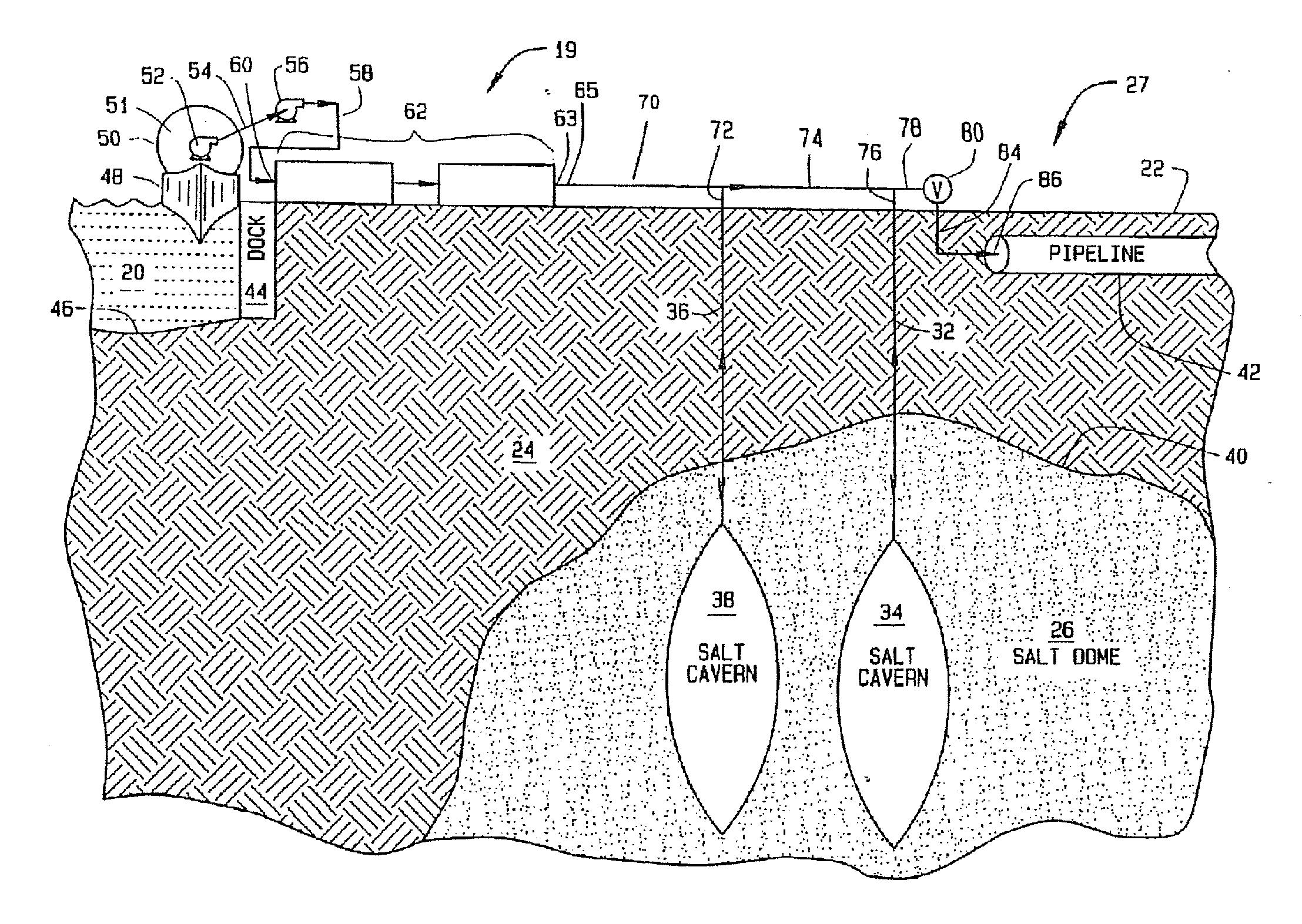
[0068]EXAMPLE #1. This hypothetical example is designed to give broad operational parameters for the Bishop One-Step Process conducted at or near dockside as shown in FIG. 1. A number of factors must be considered when designing the facility 19 including the type of cold fluid and warmant that will be used. Conventional instrumentation for process measurement, control and safety are included in the facility as needed including but not limited to: temperature and pressure sensors, flow measurement sensors, overpressure reliefs, regulators and valves. Various input parameters must also be considered including, pipe geometry and length, flow rates, temperatures and specific heat for both the cold fluid and the warmant. Various output parameters must also be considered including the type, size, temperature and pressure of the uncompensated salt cavern. For...


PUM

PropertyMeasurementUnit
pressureaaaaaaaaaa
pressuresaaaaaaaaaa
temperaturesaaaaaaaaaa

Abstract

In the past, “compensated” salt caverns have operated with a compensating liquid, such as brine to displace a stored liquid, such as crude oil, when the stored liquid is needed on the surface. Virtually all of the stored liquid in a compensated salt cavern can be expelled from the salt cavern when it is filled with the compensating liquid. In the past, “uncompensated” salt caverns have been used to store gases, such as natural gas. Uncompensated caverns operate without any compensating liquid; instead they rely on pressure. Some of the stored gas (cushion gas) must always be left in an uncompensated salt cavern. This invention breaks with convention and uses a compensating liquid in a salt cavern to store gases which is a technique believed to be previously unknown. “Cushion gas” is not required because the compensating liquid displaces virtually all of the gas in the salt cavern.

Description

CROSS-REFERENCE TO RELATED APPLICATIONS[0001]This application is a continuation of U.S. application Ser. No. 11 / 307,806 filed on Feb. 23, 2006, said application being is a continuation-in-part of U.S. application Ser. No. 10 / 907,330 filed on Mar. 29, 2005 and issued on Mar. 2, 2006 as U.S. Pat. No. 7,036,325, said application being a continuation of U.S. application Ser. No. 10 / 709,153 filed on Apr. 16, 2004 and issued on Sep. 20, 2005 as U.S. Pat. No. 6,945,055; said application being a continuation of U.S. application Ser. No. 10 / 384,156 filed on Mar. 7, 2003 and issued on Nov. 9, 2004 as U.S. Pat. No. 6,813,893; which is a continuation-in-part of application Ser. No. 10 / 246,954 filed on Sep. 18, 2002 and issued on May 25, 2004 as U.S. Pat. No. 6,739,140; which claims priority of U.S. provisional patent application 60 / 342,157 filed Dec. 19, 2001.BACKGROUND OF THE INVENTION[0002]Much of the natural gas used in the United States is produced along the Gulf Coast. There is an extensiv...

Claims


Application Information

Patent Timeline
Patent Type & Authority Applications(United States)
IPC IPC(8): B65G5/00C10L3/10F17C3/00F17C5/06F17C7/00F17C9/02
CPCF17C1/007F17C3/005F17C5/06F17C7/00F17C9/02F17C2201/052F17C2205/013F17C2205/0142F17C2205/0323F17C2205/0332F17C2205/0338F17C2205/0364F17C2221/012F17C2221/017F17C2221/033F17C2221/035F17C2223/0115F17C2223/0123F17C2223/0153F17C2223/0161F17C2223/033F17C2223/035F17C2223/036F17C2223/043F17C2223/047F17C2225/0115F17C2225/0123F17C2225/035F17C2225/036F17C2225/043F17C2225/047F17C2227/0135F17C2227/0157F17C2227/0164F17C2227/0185F17C2227/0192F17C2227/0309F17C2227/0316F17C2227/0318F17C2227/0323F17C2227/033F17C2227/0337F17C2227/0341F17C2227/0348F17C2227/0351F17C2227/0388F17C2227/039F17C2227/0393F17C2227/0395F17C2227/041F17C2227/046F17C2250/043F17C2250/0439F17C2250/0443F17C2250/0456F17C2250/061F17C2250/0626F17C2250/0636F17C2250/0657F17C2260/025F17C2265/027F17C2265/05F17C2265/068F17C2270/0105F17C2270/0121F17C2270/0123F17C2270/0136F17C2270/0152F17C2270/016F17C2270/0163F17C2270/05Y02E60/321Y02E60/32Y10T137/0346Y10T137/402
Inventor BISHOP, WILLIAM M.
Owner CONVERSION GAS IMPORTS
Why Eureka
Try Eureka