Method And Apparatus For Referencing A MEMS Device

a technology of mems mirror and reference device, which is applied in the field of optical devices, can solve the problems of mechanical stresses deflecting the mirror, the tilt angle drift and the long-term instability of the mems mirror

Active Publication Date: 2009-01-08
LUMENTUM OPERATIONS LLC
View PDF6 Cites 17 Cited by
  • Summary
  • Abstract
  • Description
  • Claims
  • Application Information

AI Technical Summary

Benefits of technology

[0018]In accordance with another aspect of the invention there is further provided a method for lessening an insertion loss of an optical module including: a mirror and an actuator for tilting said mirror in response to applying a control signal to the actuator; an emitting planar array of waveguides for emitting light; a receiving planar array of waveguides for receiving light; and a coupler for coupling a light emitted by a waveguide of the emitting planar array to the mirror, and for coupling the light reflected from the mirror to a waveguide of the receiving planar array, wherein the module is usable for routing an optical signal from a waveguide of the emitting planar array into a waveguide of the receiving planar array, wherein the method comprises:
[0019]dithering the control signal applied to the actuator and measuring AC and DC components of the power of light coupled into any of two, or both outer waveguides of the receiving planar array; determining, from said AC and DC components of the power of light, a value of a control signal which, when applied, would reduce the insertion loss of the optical module; and applying the control signal of said value to the actuator;

Problems solved by technology

One disadvantage of MEMS mirrors is their long-term instability.
Since MEMS are generally electrostatically actuated, typically using a parallel plate capacitor structure, a small change in the accumulated charge due to slow charge migration or small changes in the electrical properties of the structure can lead to drift of a MEMS mirror tilt angle.
The mirrors themselves are very thin, and deposition of a reflective material onto the mirror can result in mechanical stresses which deflect the mirror over time.
In addition, embedding a sensor complicates a MEMS design, with the required accuracy of micromirror tilt being sometimes difficult to achieve.
The optical feedback techniques of this prior art suffer from being bulky and difficult to implement, especially on a large number of emitting and / or receiving optical fibers.
Placing a large number of position sensitive detectors such as a charge coupled device (CCD) or a quadrant detector into an optical switch module is impractical.
Tapping off a portion of the signal increases insertion loss for the signal going through the module, which is detrimental.

Method used


Image

  • Method And Apparatus For Referencing A MEMS Device
  • Method And Apparatus For Referencing A MEMS Device
  • Method And Apparatus For Referencing A MEMS Device

Examples


Embodiment Construction

[0049]While the present teachings are described in conjunction with various embodiments and examples, it is not intended that the present teachings be limited to such embodiments. On the contrary, the present teachings encompass various alternatives, modifications and equivalents, as will be appreciated by those of skill in the art. In FIG. 1 and FIG. 2, like numerals refer to like parts.

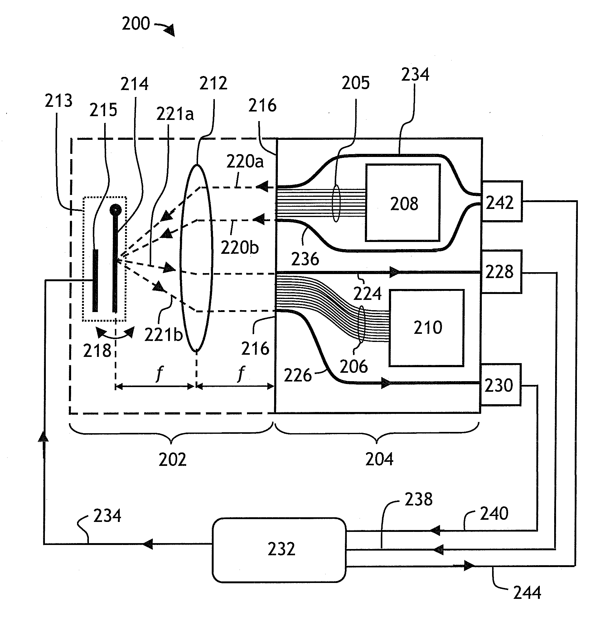
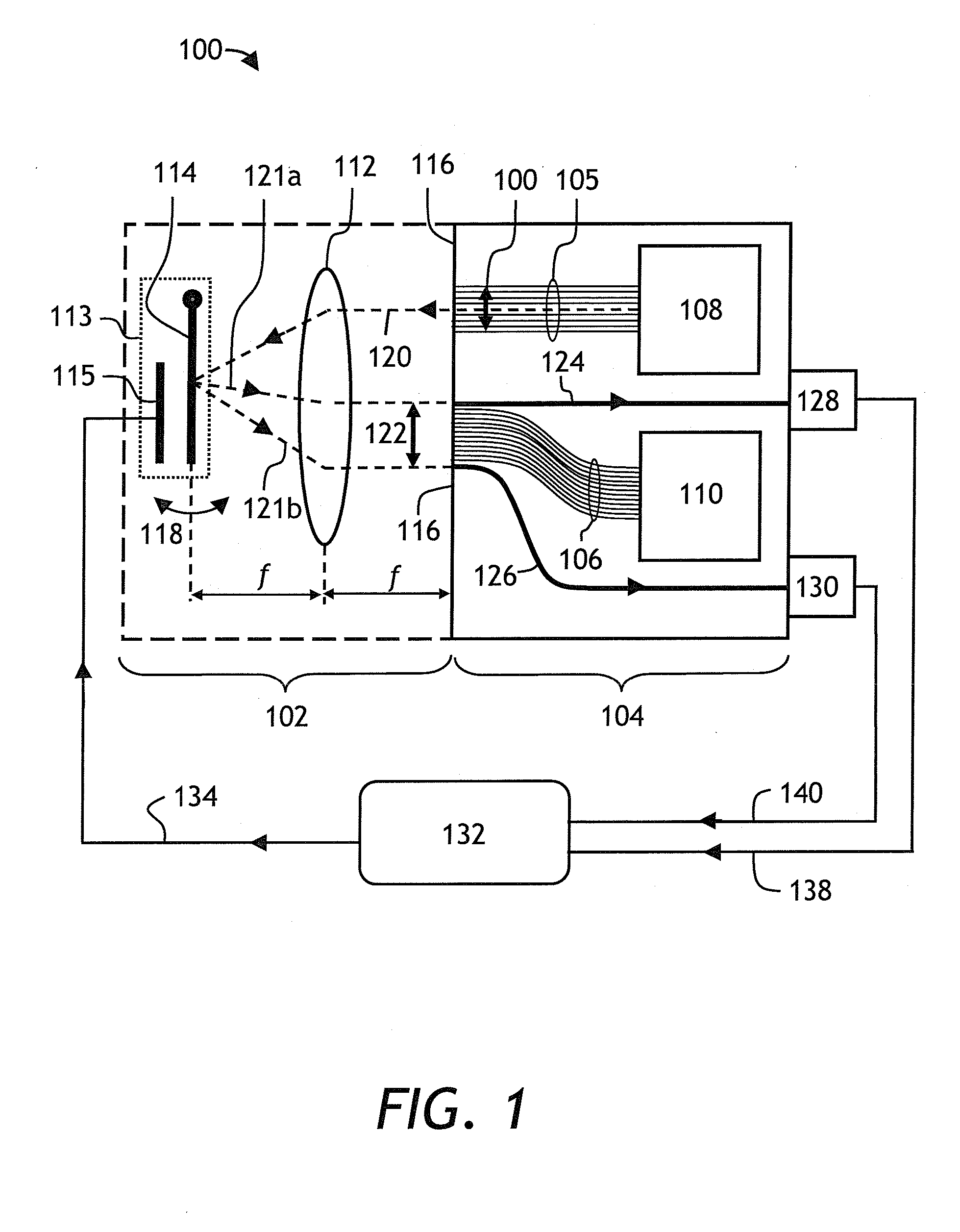
[0050]Turning now to FIG. 1, a hybrid MEMS-PLC optical module 100, usable for switching information-carrying optical signals in an optical network, is shown. The module 100 consists of a free space optical part 102 and a PLC part 104, wherein the free space optical part 102 provides optical switching between waveguides of an emitting waveguide array 105 and waveguides of a receiving waveguide array 106 of PLC 104. Generally speaking, PLC 104 may carry out a number of additional functions performed on input and output optical signals, such as wavelength multiplexing and demultiplexing, and, or attenu...


PUM

PropertyMeasurementUnit
voltageaaaaaaaaaa
poweraaaaaaaaaa
angle of tiltaaaaaaaaaa

Abstract

A method and an apparatus for calibrating a MEMS actuator of a hybrid MEMS-PLC optical switch or router is described. Two calibrating waveguides, embedded monolithically adjacent to the waveguides that provide the PLC output functions, are used for referencing a MEMS mirror tilt angle by maximizing optical coupling of light, reflected off the MEMS mirror, into one or each of the two calibrating waveguides. The input light is provided by either a waveguide carrying a live optical signal, or by a special input waveguide, coupled to an LED, for providing a calibrating light. Two emitting waveguides, embedded monolithically adjacent to the waveguides that provide the PLC input functions, can be used.

Description

CROSS-REFERENCE TO RELATED APPLICATIONS[0001]The present invention claims priority from U.S. Patent Application No. 60 / 948,309 filed Jul. 6, 2007 entitled “MEMS PLC Based Angular Referencing Scheme”, which is incorporated herein by reference.TECHNICAL FIELD[0002]The present invention is related to optical devices employing micro-electro-mechanical systems (MEMS), and in particular to methods of referencing of MEMS utilized in such devices.BACKGROUND OF THE INVENTION[0003]Fiberoptic communication systems frequently require optical signals, carried by optical fibers, to be switched and routed from one fiber to another. Recently, micro-electro-mechanical systems (MEMS) have found a widespread use in devices that switch light between input and output optical fibers. MEMS are fabricated on a silicon substrate using modified semiconductor fabrication technologies, normally used to make electronics. Many MEMS used for optical switching contain electrostatically actuated tiltable micromirro...

Claims


Application Information

Patent Timeline
Patent Type & Authority Applications(United States)
IPC IPC(8): G01J1/42G01N21/55
CPCG01D18/004G01D5/30
Inventor DUGGAN, PHILIPSHEN, JINXICRAFTS, DOUGLAS E.
Owner LUMENTUM OPERATIONS LLC
Why Eureka
Try Eureka