
Analog front-end circuit, semiconductor device, and electronic instrument

Inactive Publication Date: 2009-01-08
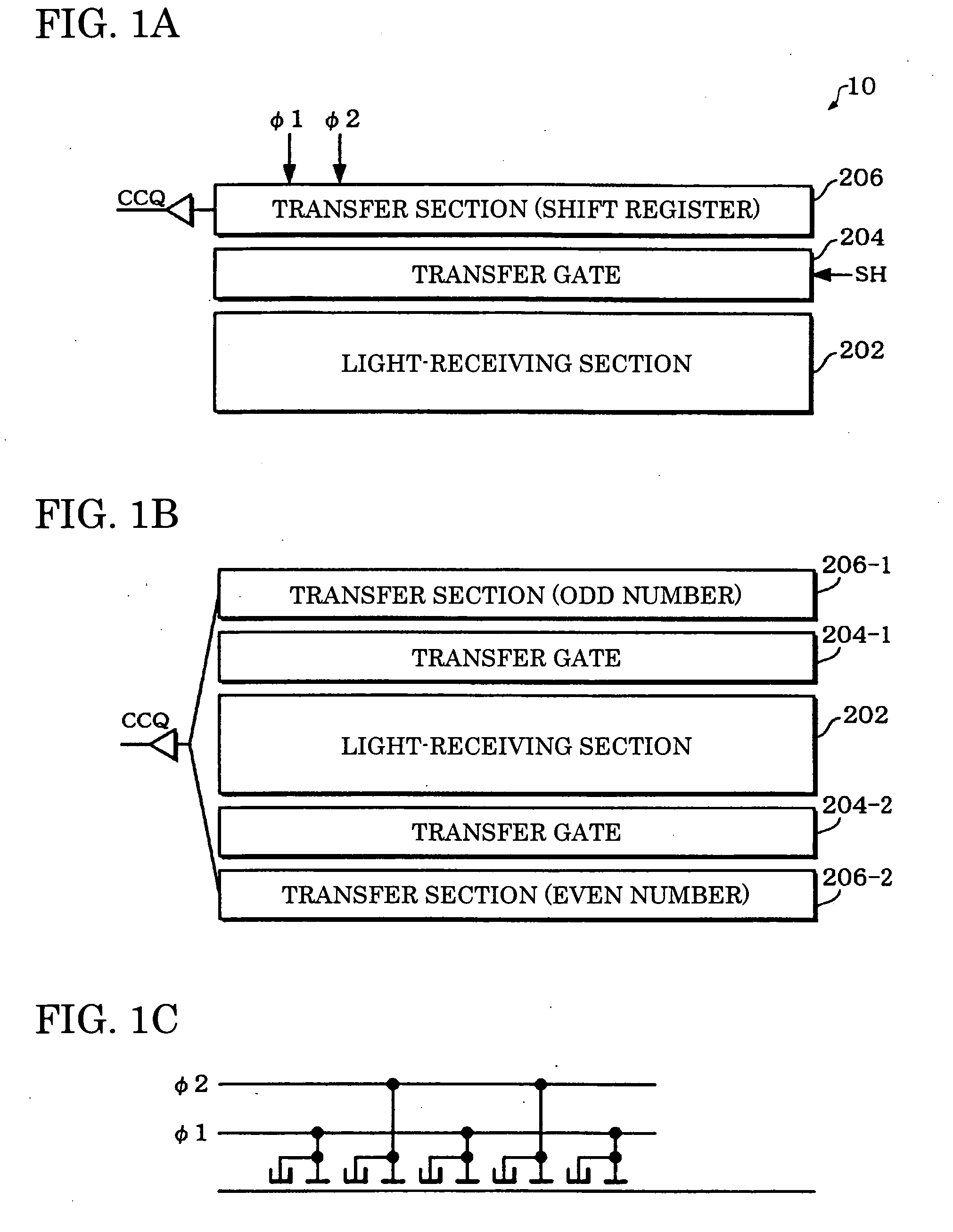
SEIKO EPSON CORP
View PDF3 Cites 8 Cited by
  • Summary
  • Abstract
  • Description
  • Claims
  • Application Information

AI Technical Summary

Problems solved by technology

This results in an increase in circuit scale.
Moreover, since the circuit must be changed depending on the image sensor, an increase in development period, an increase in development cost, or the like occurs.

Method used


Image

  • Analog front-end circuit, semiconductor device, and electronic instrument
  • Analog front-end circuit, semiconductor device, and electronic instrument
  • Analog front-end circuit, semiconductor device, and electronic instrument

Examples


Embodiment Construction

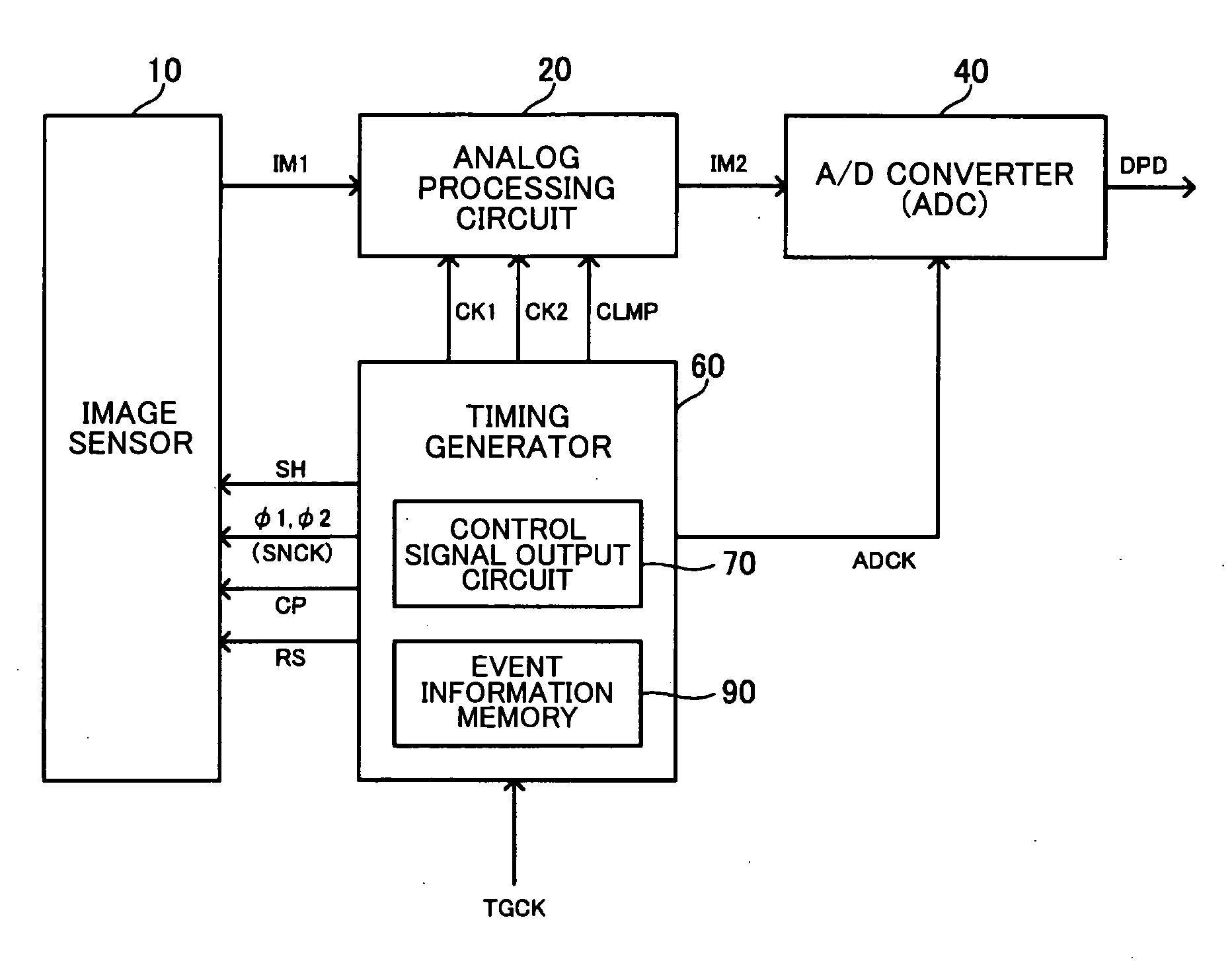
[0035]Aspects of the invention may provide an analog front-end circuit which enables efficient generation of control signals, a semiconductor device, and an electronic instrument including the same.

[0036]According to one embodiment of the invention, there is provided an analog front-end circuit comprising:

[0037]an analog processing circuit that receives an analog input image signal from an image sensor, performs a given process on the analog input image signal, and outputs an analog image signal;

[0038]an A / D converter that A / D-converts the analog image signal output from the analog processing circuit; and

[0039]a timing generator that generates a plurality of control signals that are supplied to the image sensor,

[0040]the timing generator including:

[0041]an event information memory; and

[0042]a control signal output circuit that generates the plurality of control signals based on information read from the event information memory, and outputs the plurality of control signals that have...


PUM


Abstract

An analog front-end circuit includes an analog processing circuit, an A / D converter, and a timing generator that generates a plurality of control signals that are supplied to an image sensor. The timing generator includes an event information memory, and a control signal output circuit that generates the control signals based on information read from the event information memory and outputs the generated control signals. The event information memory stores a pixel number and change event occurrence information at each address. The change event occurrence information specifies a control signal that undergoes a signal level change event at the pixel number. The control signal output circuit generates the control signals based on the pixel number and the change event occurrence information read from the event information memory and outputs the generated control signals.

Description

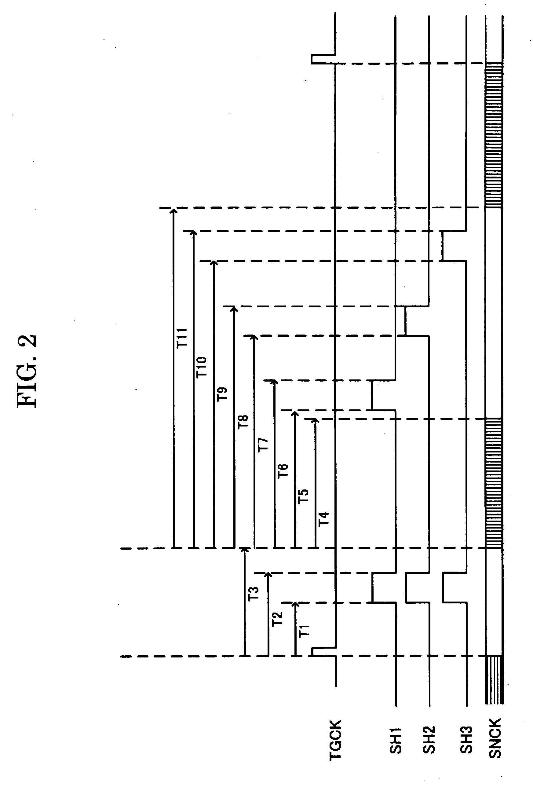
[0001]Japanese Patent Application No. 2007-37824 filed on Feb. 19, 2007, is hereby incorporated by reference in its entirety.BACKGROUND OF THE INVENTION[0002]The present invention relates to an analog front-end circuit, a semiconductor device, an electronic instrument, and the like.[0003]In an image sensor such as a CCD or CMOS sensor used for electronic instruments such as an image reader, an image signal (stored charge) obtained by a light-receiving section of the image sensor is transferred from the light-receiving section to a transfer section based on a shift signal supplied to the image sensor. The image signal is sequentially shifted by the transfer section based on a drive clock signal and is output to the outside.[0004]JP-A-2004-297146 discloses related-art technology relating to a circuit which generates image sensor control signals such as a shift signal (shift clock signal) and a drive clock signal. In Patent Document 1, the shift signal is generated by setting the signa...

Claims


Application Information

Patent Timeline
IPC IPC(8): H04N5/228G06T1/00H04N1/028H04N5/335H04N5/341H04N5/369H04N5/372H04N5/376H04N5/378
CPCH04N5/3765H04N5/335H04N25/00H04N25/745
Inventor HASEGAWA, TOMONAGAMIZUTA, MASAHIKO
Owner SEIKO EPSON CORP
Learn More