
System and method for measuring and recording distance

Inactive Publication Date: 2009-01-08
VEHICLE SERVICE GROUP LLC
View PDF11 Cites 22 Cited by
  • Summary
  • Abstract
  • Description
  • Claims
  • Application Information

AI Technical Summary

Benefits of technology

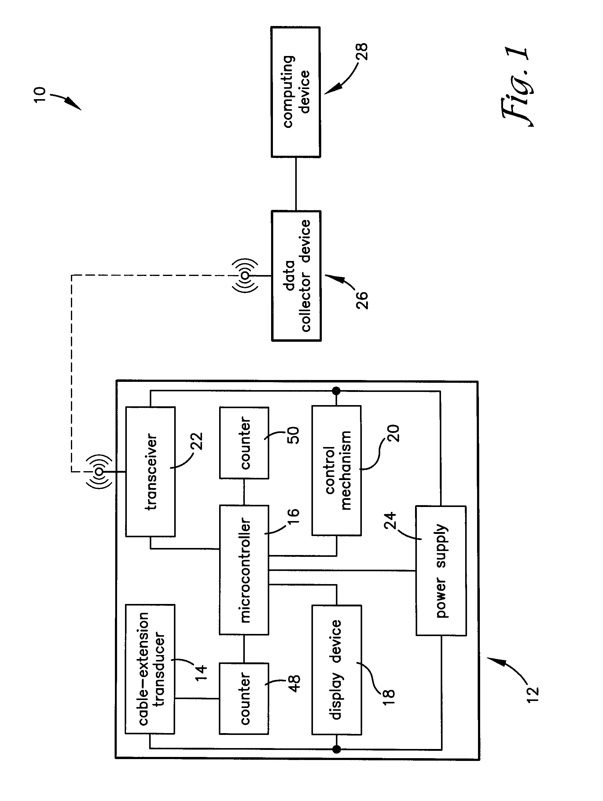
[0006]The present invention provides a system and method for more accurately and efficiently measuring and recording distances, such as between structures or reference points on, for example, vehicles. More specifically, the present invention uses a cable-extension transducer to provide actual distance data for comparison with ideal distance data in order to identify differences therebetween which could, for example, indicate a need for structural adjustment when repairing a vehicle.
[0011]From the description step forth herein, it will be appreciated that the present invention provides several advantages over the prior art, including, for example, overcoming the prior art limitation on the maximum length of the cable and, therefore, the maximum distance that can be measured by associating the rotational sensor with the wheel, rather than the spool, which allows for winding the cable about the spool in multiple layers. Additionally, the present invention substantially automatically both determines distance and communicates the determined distance to a computing device for further analysis, thereby minimizing the potential errors of the prior art from incorrectly reading a distance scale and / or incorrectly recording the determined distance.

Problems solved by technology

Unfortunately, the cable can only be wound on the spool in a single layer because additional layers would have different radii and therefore correspond to different distances, which limits the maximum length of the cable and, therefore, the maximum distance that can be measured.
When a vehicle has been damaged, its structure may be deformed or forced out of alignment.
However, it is sometimes desirable to measure distances between substructures or other reference points in locations which do not allow for use of, or do not allow for convenient use of, such laser-based devices.
As such, it will be appreciated that the use of conventional tape measures creates a significant risk of error in initially reading the tape measure and in recording the measured distance.

Method used


Image

  • System and method for measuring and recording distance
  • System and method for measuring and recording distance
  • System and method for measuring and recording distance

Examples


Embodiment Construction

, set forth below.

BRIEF DESCRIPTION OF THE DRAWING FIGURES

[0013]The present invention is described herein with reference to the following drawing figures, which are not necessarily to scale:

[0014]FIG. 1 is a block diagram of the major components of an embodiment of the system of the present invention;

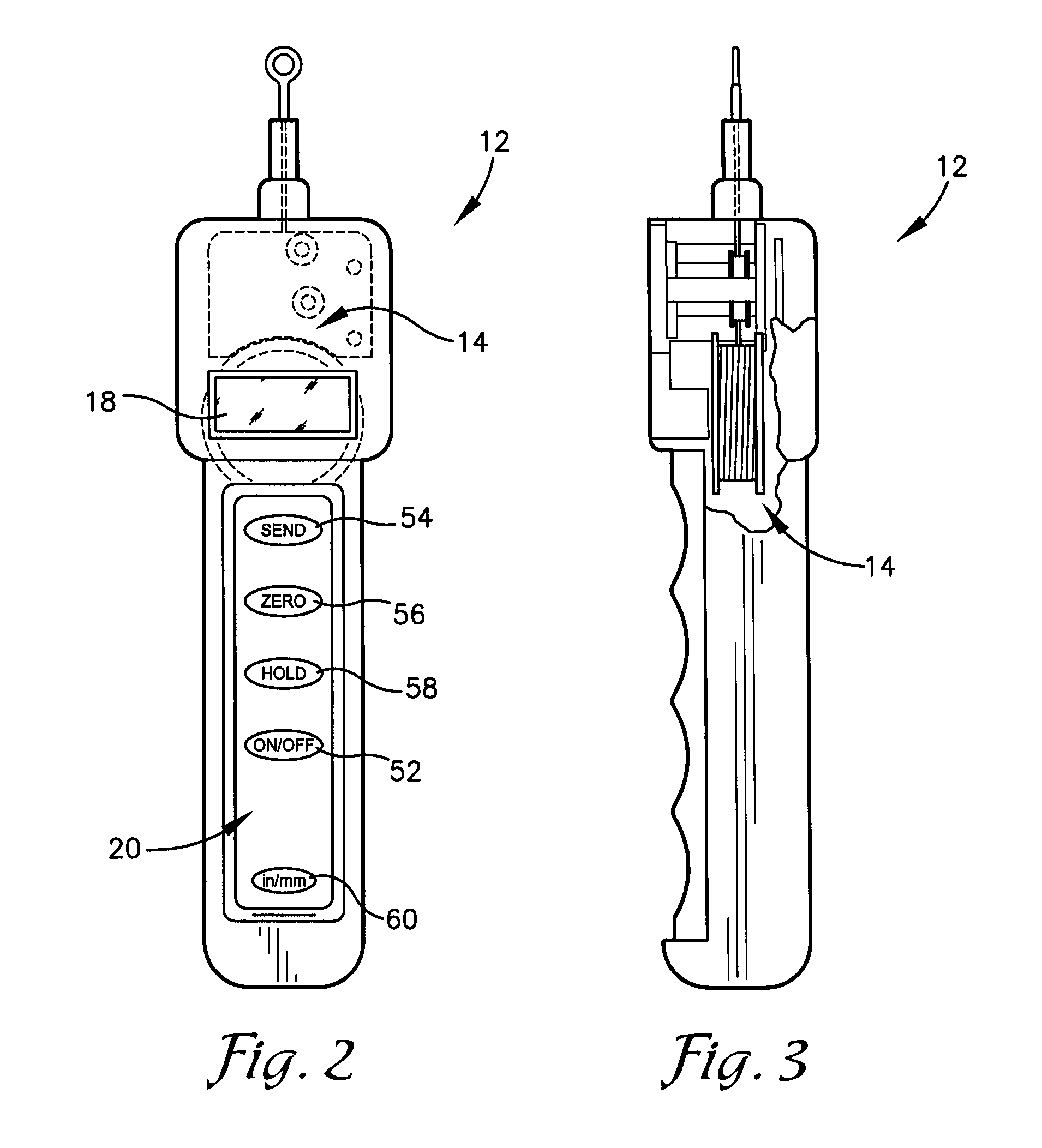
[0015]FIG. 2 is a front elevation view of a measurement device component of the system of FIG. 1;

[0016]FIG. 3 is a side elevation view of the measurement device component of FIG.2;

[0017]FIG. 4 is a front elevation view of a portion of a cable-extension transducer subcomponent of the measurement device component of FIG. 2;

[0018]FIG. 5 is a side elevation view of the cable-extension transducer subcomponent of FIG. 4; and

[0019]FIG. 6 is a flowchart of steps involved in practicing an embodiment of the method of the present invention using the system of FIG. 1.

DETAILED DESCRIPTION OF THE INVENTION

[0020]With reference to the drawings figures, a system and method is herein described, shown, an...


PUM


Abstract

A system (10) and method for measuring and recording distances, such as between structures or reference points on vehicles. The system includes one or more measurement devices (12), each having a cable-extension transducer (14) for generating an electronic signal corresponding to the distance, a microprocessor(16) for determining the distance based upon the electronic signal, and a transceiver (22) operable to wirelessly transmit the distance to a data collection device (26) connected to a computing device (28). The cable-extension transducer (14) is wound about a spool (38) and directed around a wheel (40) such that the wheel (40) turns as the cable (36) is extended or retracted over the distance, thereby allowing for winding the cable (36) in multiple layers about the spool (38). The computing device (28) compares the measured distance to an ideal distance, and reports any difference therebetween.

Description

RELATED APPLICATIONS[0001]The present non-provisional patent application claims priority benefit of any earlier-filed provisional patent application of the same title, Ser. No. 60 / 947,529, filed Jul. 2, 2007. The identified earlier-filed application is hereby incorporated by reference as though fully set forth herein.FIELD OF THE INVENTION[0002]The present invention relates to systems and method for measuring and recording distances, such as between structures or reference points on vehicles. More specifically, the present invention concerns such a system and method using a cable-extension transducer to provide actual distance data which can be compared with ideal distance data in order to identify differences therebetween which could, for example, indicate a need for structural adjustment when repairing a vehicle.BACKGROUND OF THE INVENTION[0003]Cable-extension transducers (CETs), also called “string pots”, “draw wire sensors”, “string encoders”, and “yo-yo sensors”, allow for meas...

Claims


Application Information

Patent Timeline
IPC IPC(8): G08C17/02B65H61/00
CPCG01B3/1084G01B7/026G01B3/11H04Q9/00G01B2210/58
Inventor FLANNIGAN, WILLIAM C.JOHNSON, BRENT L.ADAIR, JAROD O.PHILLIPS, TERRY A.
Owner VEHICLE SERVICE GROUP LLC
Learn More