
Systems and Methods for Using a Combustion Dynamics Tuning Algorithm with a Multi-Can Combustor

Active Publication Date: 2009-01-01
GENERAL ELECTRIC CO
View PDF10 Cites 50 Cited by
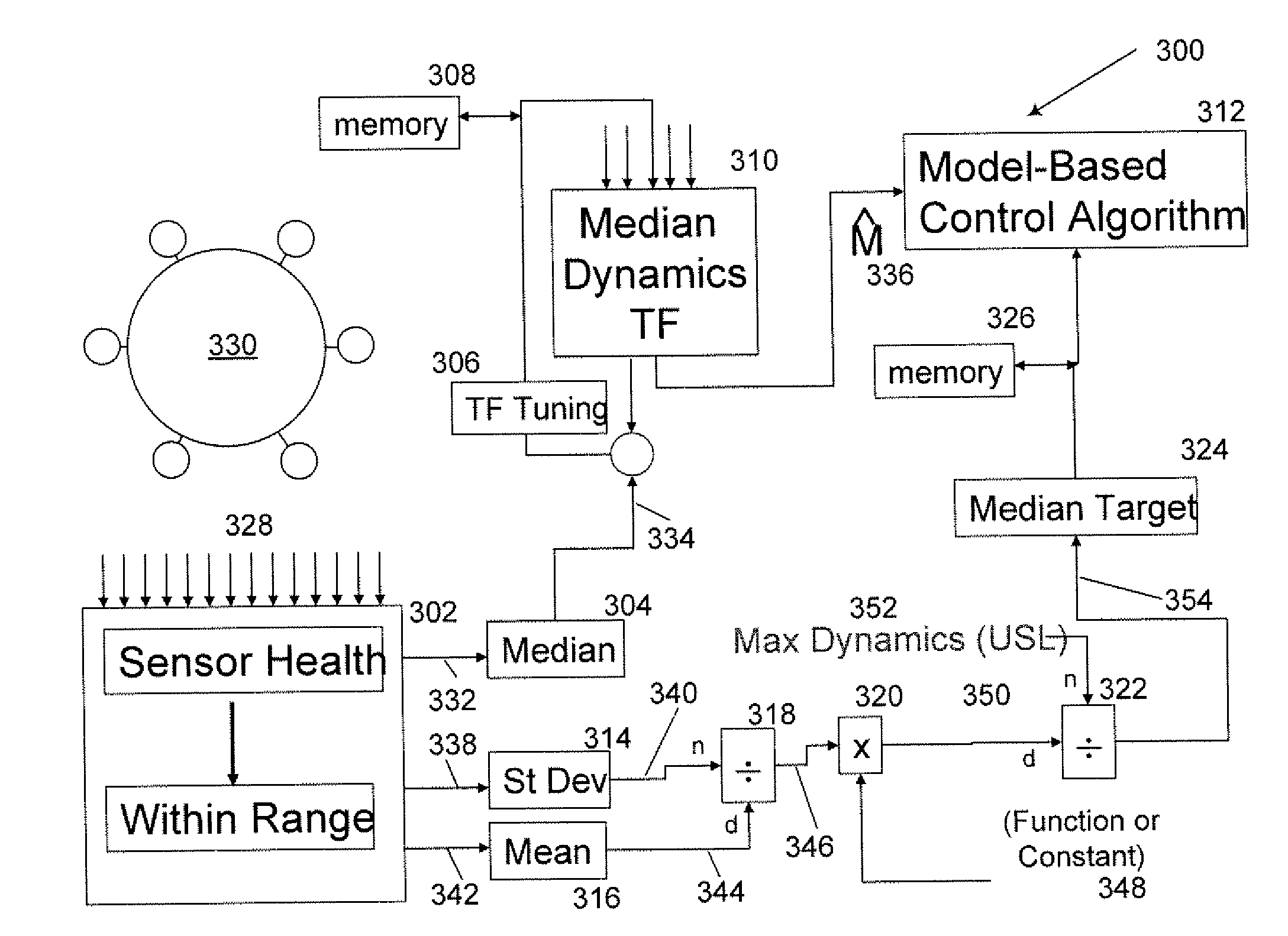
  • Summary
  • Abstract
  • Description
  • Claims
  • Application Information

AI Technical Summary

Benefits of technology

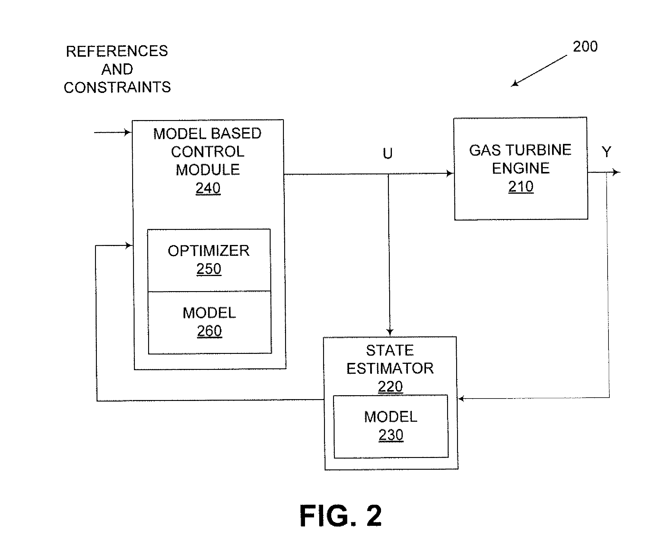
[0005]Embodiments of the invention can address some or all of the needs described above. Embodiments of the invention are directed generally to systems and methods for using a combustion dynamics tuning algorithm with a multi-can combustor. According to one embodiment of the invention, a method for controlling a gas turbine engine with an engine model can be implemented for an engine comprising multiple cans. The method can include obtaining operating frequency information associated with multiple cans of the engine. In addition, the method can include determining variation between operating frequency information of at least two cans. Furthermore, the method can include determining a median value based at least in part on the variation. Moreover, the method can include determining whether the median value exceeds at least one operating threshold. The method can also include im

Problems solved by technology

Design and operation of a combustion system in a rotary machine such as a gas turbine engine can be complex.
In some instances, one or more sensors associated with a combustor, such as a single can combustor or can annular-type combustor, may provide poor or errant data or measurements.
For example, a sensor may fail during combustor operation, and data from the sensor may cease or otherwise be considered errant or poor.
If more than one sensor provides poor or errant data or measurements, such data or measurements may be input to the conventional dynamics tuning algorithm, and decreased efficiency of the combustor can result.
In other instances, poor tuning or decreased efficiency can result in excessive vibration in or damage to the combustor.

Method used


Image

  • Systems and Methods for Using a Combustion Dynamics Tuning Algorithm with a Multi-Can Combustor
  • Systems and Methods for Using a Combustion Dynamics Tuning Algorithm with a Multi-Can Combustor
  • Systems and Methods for Using a Combustion Dynamics Tuning Algorithm with a Multi-Can Combustor

Examples


Embodiment Construction

[0016]The invention now will be described more fully hereinafter with reference to the accompanying drawings, in which example embodiments of the invention are shown. This invention may, however, be embodied in many different forms and should not be construed as limited to the example embodiments set forth herein; rather, these embodiments are provided so that this disclosure will convey the scope of the invention to those skilled in the art. Like numbers refer to like elements throughout.

[0017]Embodiments of the invention are described below with reference to block diagrams and schematic illustrations of methods and systems according to embodiments of the invention. It will be understood that each block of the diagrams, and combinations of blocks in the diagrams can be implemented by computer program instructions. These computer program instructions may be loaded onto one or more general purpose computers, special purpose computers, or other programmable data processing apparatus t...


PUM


Abstract

Embodiments of the invention can provide systems and methods for using a combustion dynamics tuning algorithm with a multi-can combustor. According to one embodiment of the invention, a method for controlling a gas turbine engine with an engine model can be implemented for an engine comprising multiple cans. The method can include obtaining operating frequency information associated with multiple cans of the engine. In addition, the method can include determining variation between operating frequency information of at least two cans. Furthermore, the method can include determining a median value based at least in part on the variation. Moreover, the method can include determining whether the median value exceeds at least one operating threshold. The method can also include implementing at least one engine control action to modify at least one of the operating frequencies if at least one operating threshold is exceeded.

Description

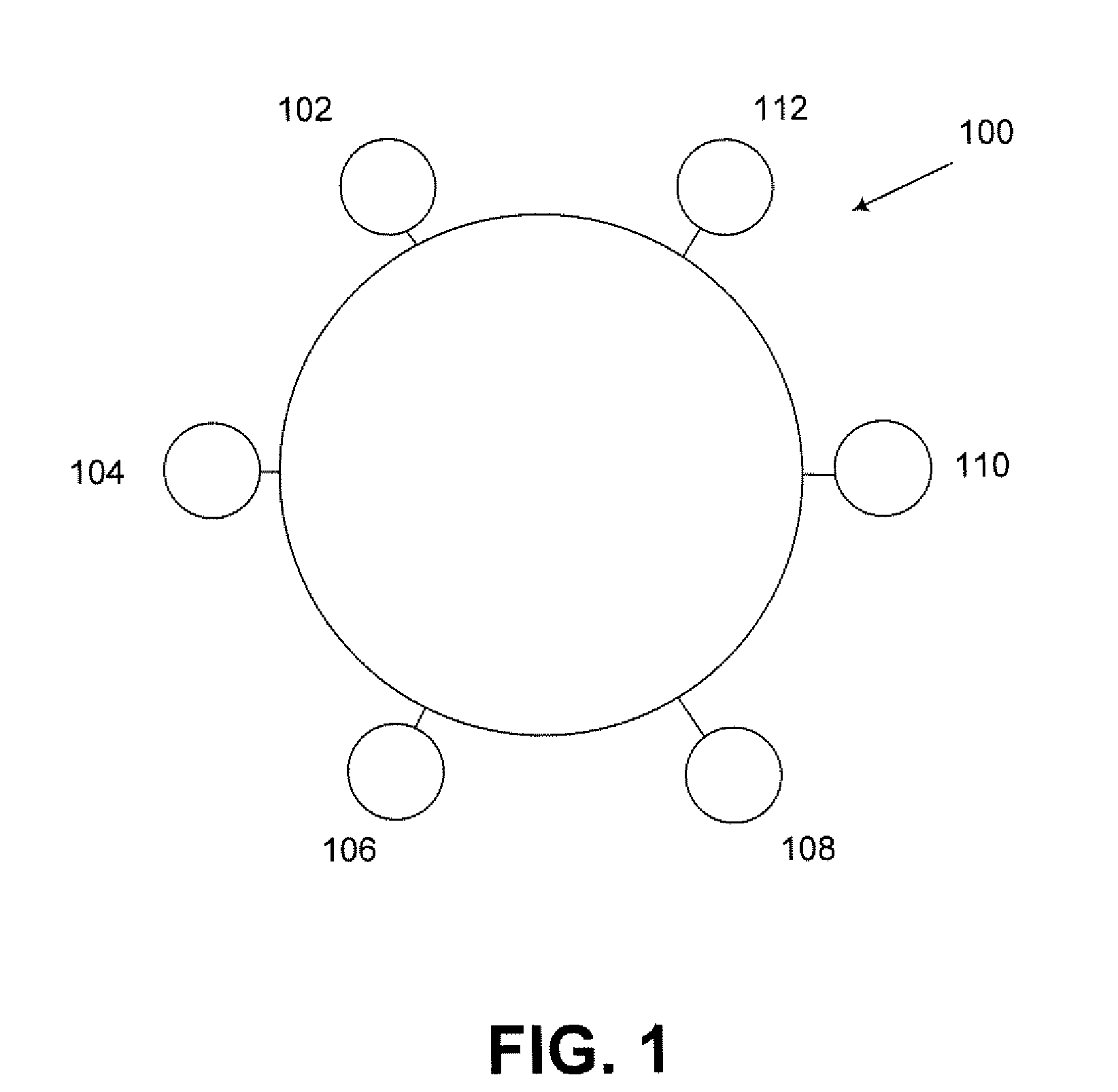
FIELD OF THE INVENTION[0001]The invention relates to combustion dynamics control, and more particularly, to systems and methods for using a combustion dynamics tuning algorithm with a multi-can combustor.BACKGROUND OF THE INVENTION[0002]Design and operation of a combustion system in a rotary machine such as a gas turbine engine can be complex. To operate such engines, conventional combustion dynamics tuning algorithms can utilize one or more sensors associated with various engine components to obtain performance and operating characteristics of the engine. For example, a General Electric Model GE-10 single can combustor can utilize outputs from multiple combustion dynamic sensors to tune the combustor using a conventional dynamics tuning algorithm. In another example, a can annular-type combustor, which can include multiple cans arranged in an annular-shaped configuration, can utilize inputs from multiple combustion dynamic sensors, one for each can, to tune the combustor using anot...

Claims


Application Information

Patent Timeline
IPC IPC(8): F02C9/00
CPCF02C9/28F23N5/00F23N2023/40F23N2023/44F23N2041/20Y10T477/40F23R2900/00013G05B13/041Y02T50/677F05D2270/31F05D2260/80F23R3/46F23N2223/40F23N2223/44F23N2241/20Y02T50/60
Inventor TONNO, GIOVANNIPACI, MARIATERESASTEWART, JESSE FLOYDASTI, ANTONIO
Owner GENERAL ELECTRIC CO
Learn More