
Modular intraocular implant

a module and intraocular technology, applied in the field of ocular implants, can solve the problems of reducing the amount of light passing through the lens, affecting the effect of cataract surgery, so as to facilitate the implantation during cataract surgery, facilitate post-surgical adjustment, and simple replacement of the corrective lens

Inactive Publication Date: 2009-01-01
EGGLESTON HARRY C
View PDF21 Cites 136 Cited by
  • Summary
  • Abstract
  • Description
  • Claims
  • Application Information

AI Technical Summary

Benefits of technology

"The present invention provides an adjustable ocular implant that can be implanted during cataract surgery and easily adjusted post-surgically. The implant includes a relatively soft but compressible and resilient outer or base annulus designed to fit in the lens capsule and keep the lens capsule open. There is a second concentric annulus removably seated in the outer annulus, with a rotatable annular lens mount, bearing an appropriate lens, that can be rotated to adjust and fine-tune the refractive power and focusing for hyperopia, myopia, astigmatism and accommodation with advanced magnetic model. The intraocular implant has a correction range for spherical correction of approximately +3√0π−3 diopters with probable steps of 0.50 diopters and for astigmatic correction of +1 to +4 with an overlay lens. The entire lens assembly, including its base, its button component, its bottom component, concentric stem, the ring means adapted for insertion onto the concentric stem, and the cap, will have a thickness, from the front of the lens, to the back of the lens, of less than 100-thousandths of an inch (0.100)."

Problems solved by technology

The opacification generally occurs over a period of time and the amount of light which passes through the lens decreases thereby decreasing vision.
One problem associated with intraocular lens implants is that it is necessary to decide, preoperatively, on the power of the lens.
Although the ophthalmologist (eye M.D.) uses the best techniques available, it is very difficult to accurately predict, preoperatively, the optimal power for the lens implant because of multiple variables of axial length, anterior chamber depth, corneal curvature and size, growth of the eye (pediatric cases), irregular post scleral surfaces (usually seen in the macular area) such as myopic staphylomas, mismeasurement and mislabeling of the IOL power and other human errors.
Further, since the exact amount and axis of astigmatism cannot be accurately determined until several weeks after surgery, the patient may require glasses for best vision and the lens prescription may have to be changed more than once as the eye heals over time, with normal physiological aging and because of different visual needs.
Although the foregoing devices may solve the problem of adjustment of the lens post-surgically, there have other inherent drawbacks.
Some of the adjustable lenses are complicated in design employing power sources, micromotors, microfluid pumps and electric or electrochemical circuitry.
Such complex devices can be expensive to manufacture and relatively bulky or heavy in use.

Method used


Image

  • Modular intraocular implant
  • Modular intraocular implant
  • Modular intraocular implant

Examples


Embodiment Construction

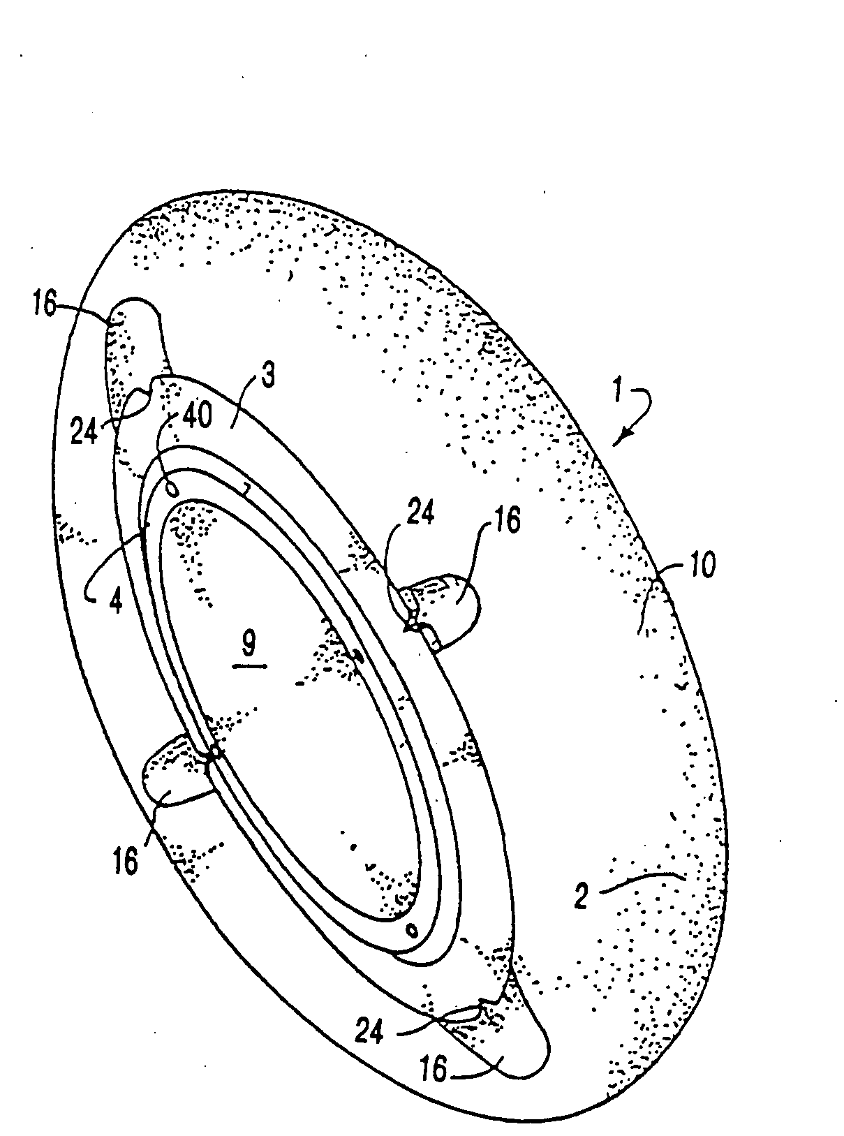
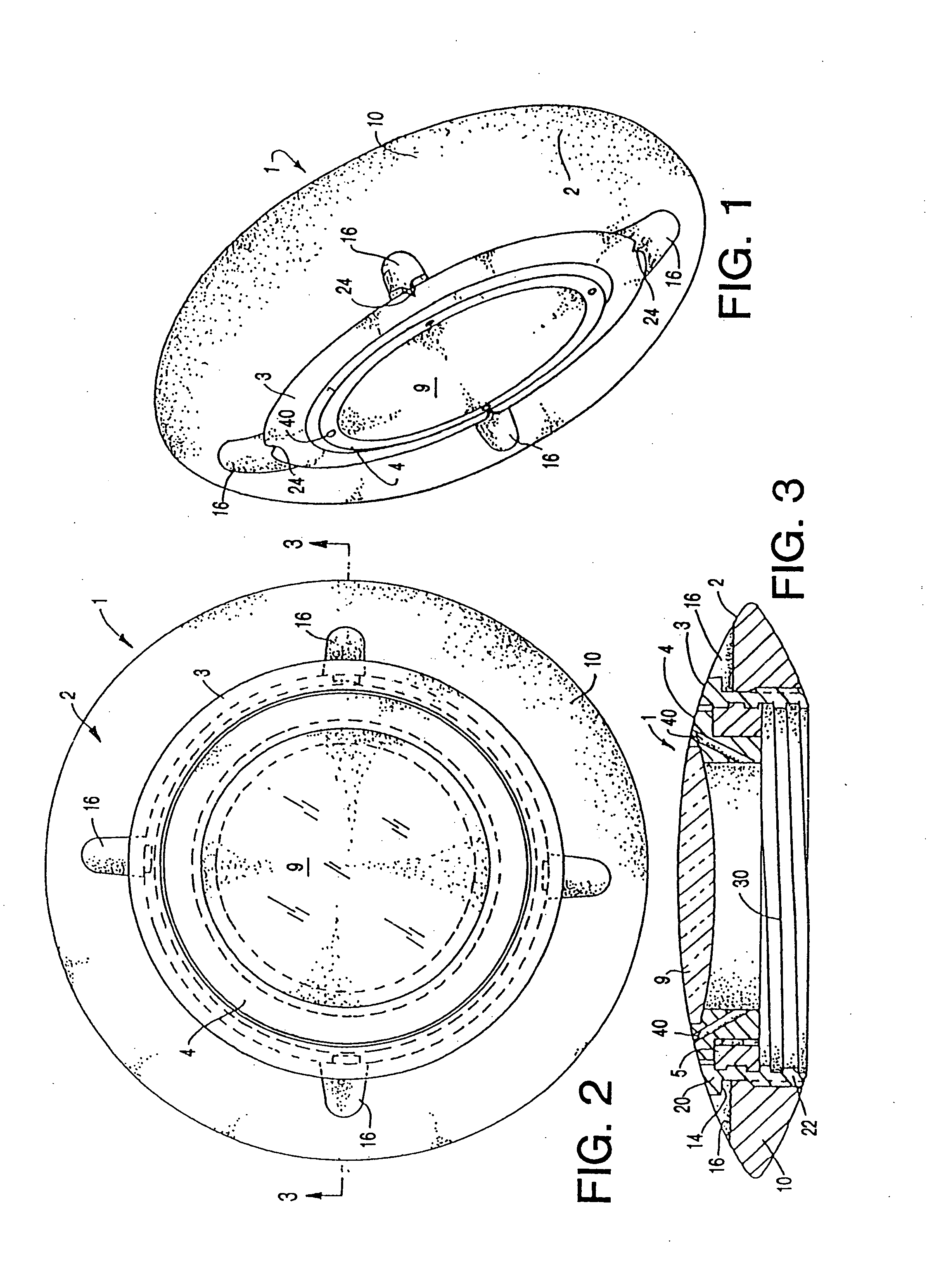
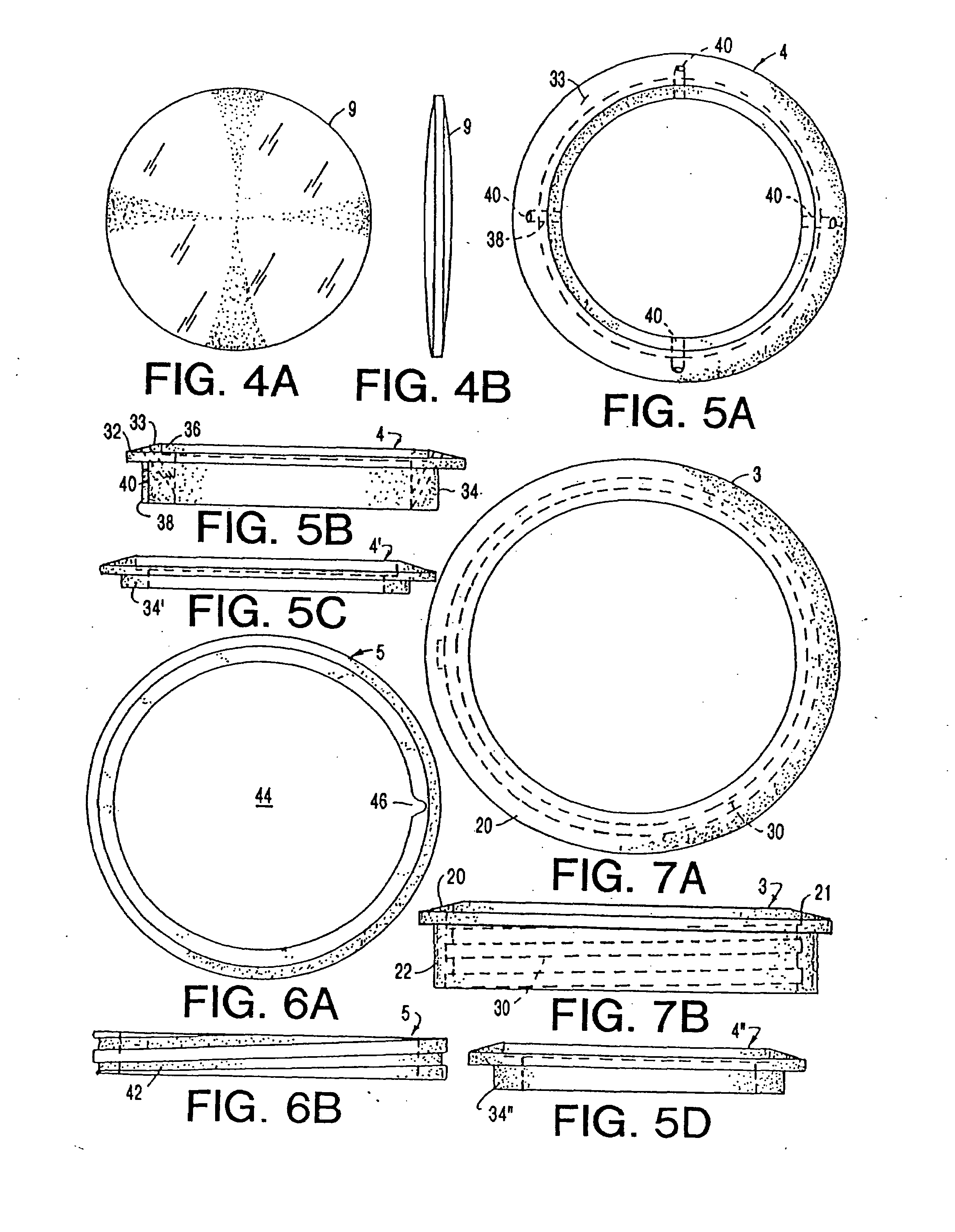
[0068]The adjustable intraocular insert of the present invention is indicated generally by reference numeral 1 in the drawings. Insert 1 has several principal components including an outer or base annulus 2 and a concentric second annulus 3. An adjustable lens mount assembly, indicated generally by reference numeral 4 in FIGS. 5A and 5B, is rotatably mounted in second annulus 3. In the preferred embodiment of FIGS. 1-3, the lens mount assembly 4 comprises two pieces, employing an externally threaded ring 5. Another embodiment of the adjustable intraocular insert, indicated generally be reference numeral 1′ in FIGS. 9A and 9B, employs a one-piece lens holder 7 (FIGS. 10A and 10B) which includes an externally threaded annular skirt 8. In any event, the lens holder seats a refractive lens 9. The various components of the adjustable intraocular insert will now be described in greater detail.

[0069]The base annulus 2, shown in greater detail in FIGS. 8A-8D, is sized and configured to fit ...


PUM


Abstract

An adjustable ocular insert to be implanted during refractive cataract surgery and clear (human) crystalline lens refractive surgery and adjusted post-surgically. The implant comprises relatively soft but compressible and resilient base annulus designed to fit in the lens capsule and keep the lens capsule open. Alternatively the annulus may be placed in the anterior or posterior chamber. The annulus can include a pair of opposed haptics for secure positioning within the appropriate chamber. A rotatable annular lens member having external threads is threadedly engaged in the annulus. The lens member is rotated to move the lens forward or backward so to adjust and fine-tune the refractive power and focusing for hyperopia, myopia and astigmatism. The intraocular implant has a power range of approximately +3√0π−3 diopters.

Description

CROSS-REFERENCE TO RELATED APPLICATIONS[0001]This application is a continuation-in-part of the patent application having Ser. No. 10 / 759,776, filed on Jan. 16, 2004, which is a continuation-in-part of the application having Ser. No. 10 / 142,486, filed on May 10, 2002, which is a continuation-in-part of the application having Ser. No. 09 / 372,493, filed on Aug. 20, 1999, which is a continuation-in-part of the application having Ser. No. 08 / 854,175, filed May 9, 1997, which is a continuation-in-part of the application having Ser. No. 08 / 764,501, filed on Dec. 12, 1996, which is a continuation-in-part of the application having Ser. No. 08 / 617,183, filed on Mar. 18, 1996, now U.S. Pat. No. 5,628,798.BACKGROUND OF THE INVENTION[0002]This invention relates generally to ocular implants and more specifically to a modular intraocular implant with an adjustable and replaceable lens.[0003]A cataract is a condition where a normally clear lens of the eye becomes progressively opaque. The opacifica...

Claims


Application Information

Patent Timeline
Patent Type & Authority Applications(United States)
IPC IPC(8): A61F2/16
CPCA61F2/16A61F2/1613A61F2/1629A61F2002/1681A61F2/1648A61F2/1694A61F2/1637A61F2210/009A61F2220/0025A61F2002/169
Inventor EGGLESTON, HARRY C.
Owner EGGLESTON HARRY C
Learn More