Focus detection optical system and imaging apparatus incorporating the same

a technology of optical systems and imaging apparatuses, applied in the field can solve the problems of affecting the accuracy of range-finding, reducing the accuracy of correlative operation, and increasing the size of focus detection optical systems, so as to achieve good enough focus detection and widen the range

Inactive Publication Date: 2009-01-01
OLYMPUS CORP
View PDF2 Cites 4 Cited by
  • Summary
  • Abstract
  • Description
  • Claims
  • Application Information

AI Technical Summary

Benefits of technology

[0060]According to the focus detection optical system of the invention, the surface apexes of the entrance- and exit-side surfaces of the re-imaging lens or double-convex lens are positioned away from the optical axis of the taking lens in the same direction and the distance of the surface apex of the entrance-side surface from the optical axis of the taking lens is set larger than the distance of the surface apex of the exit-side surface from the optical axis of the taking lens. It is thus easy to hold back the asymmetrical occurrence of field curvature at the upper and lower peripheries of the secondary object image plane, resulting in the ability to widen a range capable of good enough focus detection.
[0061]That is, it is possible to provide a focus detection optical system that is less likely to be affected by its own field curvature and so provide coverage for a wide focus detection area.

Problems solved by technology

Poor correlations between the two images would lead to a decline of correlative operation precision as their spacing is found, having adverse influences on range-finding precision.
However, such arrangement would give rise to an increase in the size of the focus detection optical system and an increase in the laid-out space.
The decline of magnification might go in favor of size reductions, but incurs a decline of focus detection precision.
Because the decline of magnification places some limitations on the movement of secondary object images on the light receptor element array, and as the pixel pitch of the light receptor element array cannot be made fine, it causes a decline of the minimum defocus quantity capable of detection.
Thus, the focus detection resolving power declines with a decline of focus detection precision.
Further, parts are more sensitive to fabrication errors, assembling errors, and adjustment errors.
On the other hand, increased magnification gives rise to an increase in the size of the focus detection optical system.
Such arrangement has a simplified construction; however, a wider range capable of focus, detection with a pair of re-imaging lenses alone would render it difficult to keep the flatness of the images, viz., field curvature in good enough shape.
Referring to how field curvature is in good enough shape, Patent Publication 4 teaches that one surface of the re-imaging lens is configured in an aspheric shape thereby correcting field curvature; however, processing into the aspheric shape is not easy, and any practical use of the aspheric surface is difficult, mainly because there is much difficulty in estimating aspheric parts.
This might work favorably for correction of field curvature, but works against decreasing the magnification (absolute value) of the focus detection optical system and achieving size reductions, because the quantity of decentration of the aperture stop and the quantity of decentration of the entrance-side surface of the re-imaging lens have the same sign whereas the quantity of decentration of the exit-side surface of the re-imaging lens has the opposite sign, rendering it difficult to make sure the refracting power of the exit-side surface.
However, more lenses are needed for the re-imaging lens, resulting in increased parts costs.

Method used


Image

  • Focus detection optical system and imaging apparatus incorporating the same
  • Focus detection optical system and imaging apparatus incorporating the same
  • Focus detection optical system and imaging apparatus incorporating the same

Examples


example 1

[0174]

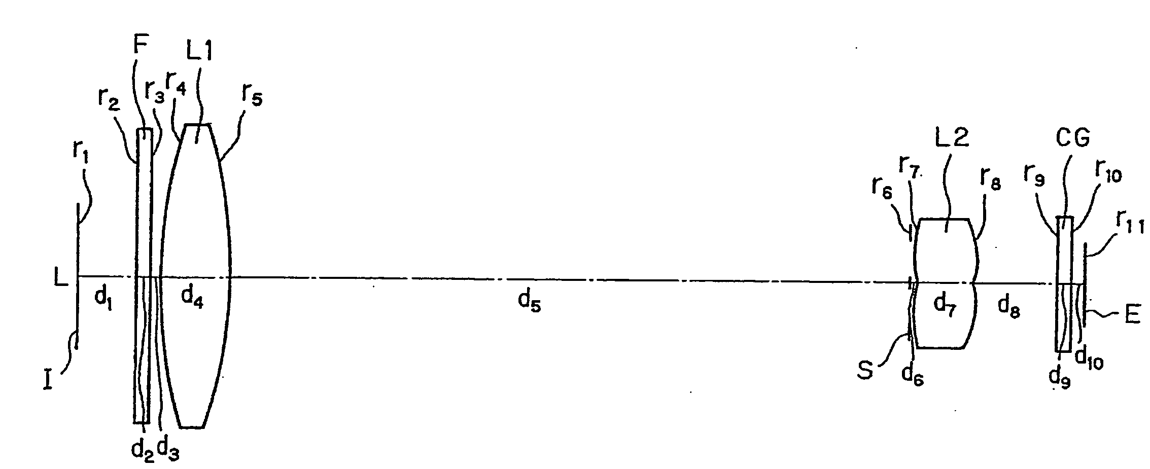
Surfacerdndνd1∞3.00228.086 (aspheric)3.521.5254255.783−26.5180.304∞0.701.5163364.145∞32.976∞ (stop)0.1676.5922.741.5254255.788−4.1584.169∞0.701.5231054.4910∞0.62image∞planeaspheric coefficientsecond surfaceK =−3.053quantity of decentrationquantity ofSurfacedecentration61.24671.60281.180

example 2

[0175]

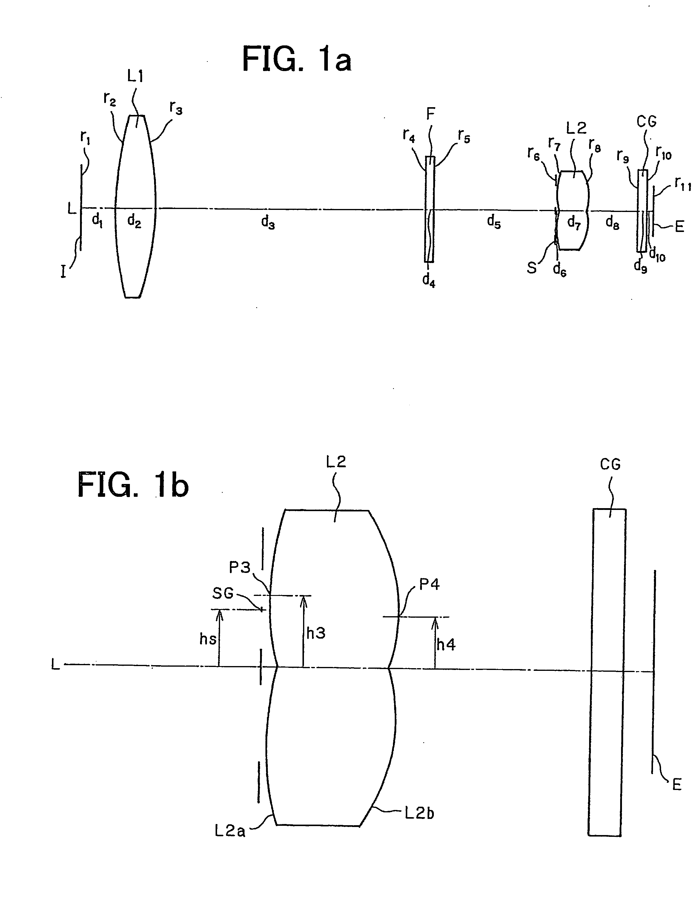
Surfacerdndνd 1∞3.00 2∞0.701.5163364.14 3∞0.50 427.549 (aspheric)3.501.5254255.78 5−27.23034.23 6∞ (stop)0.16 76.5533.201.5831359.38 84.9133.99 9∞0.701.5231054.4910∞0.62image plane∞aspheric coefficientsecond surfaceK =−3.858quantity of decentrationquantity ofSurfacedecentration61.25171.58481.171

example 3

[0176]

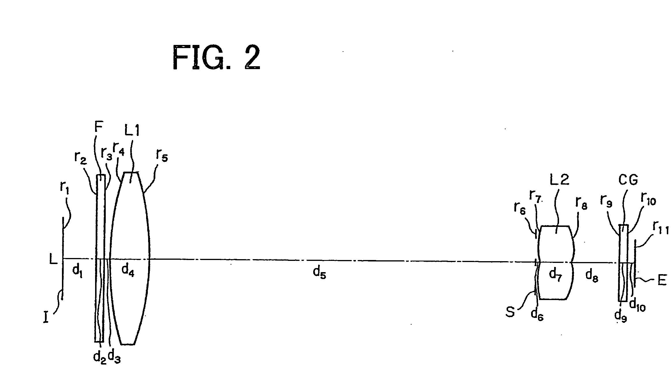
Surfacerdndνd 1∞3.00 225.361 (aspheric)3.541.4923657.86 3−23.59022.88 4∞0.701.5163364.14 5∞8.63 6∞ (stop)0.16 710.5962.901.5254255.78 8−4.6476.05 9∞0.701.5231054.4910∞0.62image plane∞aspheric coefficientsecond surfaceK =−4.840quantity of decentrationquantity ofSurfacedecentration61.19171.69981.119


PUM


Abstract

The invention relates to a focus detection optical system for digital single-lens reflex cameras or the like and an imaging apparatus incorporating the same. A pupil division optical system comprises an aperture stop having a pair of openings with an optical axis of said taking lens held between them, and a pair of re-imaging lenses, each consisting of a double-convex lens having a convex entrance-side surface and a convex exit-side surface. When, on a plane passing through the optical axis of the taking lens and the centers of gravity of the openings in the aperture stop, a surface apex is defined by a position of the convex entrance-side surface, and the convex exit-side surface, which position is extended most in a direction parallel with the optical axis of the taking lens, the surface apexes of the entrance-side surface and the exit-side surface of the double-convex lens are positioned away from the optical axis of the taking lens in the same direction, and the distance of the surface apex of the entrance-side surface from the optical axis of the taking lens is larger than the distance of the surface apex of the exit-side surface from the optical axis of the taking lens.

Description

[0001]This application claims benefit of Japanese Application No. 2007-171486 filed in Japan on Jun. 29, 2007, the contents of which are incorporated by this reference.BACKGROUND OF THE INVENTION[0002]The present invention relates generally to a focus detection optical systems for digital single-lens reflex cameras or the like and an imaging apparatus incorporating the same, and more particularly to a focus detection optical system operable to divide the pupil of a taking lens into two pupil areas so that two secondary object images are formed by a light beam passing through each pupil area to detect a relative position relation between two such secondary object images thereby detecting the focus position of the taking lens, and an imaging apparatus incorporating the same.[0003]So far, there is a phase contrast type focus detection optical system available, in which an image (primary image) formed by a taking lens is re-formed into two images on a light receptor element array via a ...

Claims


Application Information

Patent Timeline
Patent Type & Authority Applications(United States)
IPC IPC(8): G02B7/34
CPCG02B7/34
Inventor TOCHIGI, AKIYOSHI
Owner OLYMPUS CORP
Why Eureka
Try Eureka