Eureka AIR delivers breakthrough ideas for toughest innovation challenges, trusted by R&D personnel around the world.

Three-dimensional image display apparatus for displaying three-dimensional image

a three-dimensional image and display apparatus technology, applied in the direction of electrical apparatus, instruments, optics, etc., can solve the problems of affecting the display effect of three-dimensional full-color moving pictures, poor viewability, and prone to moire fringes or color moires, so as to prevent and the numerical aperture from being lowered

Inactive Publication Date: 2009-01-01
KK TOSHIBA
View PDF7 Cites 26 Cited by
  • Summary
  • Abstract
  • Description
  • Claims
  • Application Information

AI Technical Summary

Benefits of technology

[0004]The present invention relates to a three-dimensional image display apparatus for displaying a three-dimensional image.

Problems solved by technology

In this system utilizing the principle of holography, displaying a three-dimensional full-color moving picture is considered to be difficult.
Instead, since the visual field is limited, there is the problem that the viewability is poor.
In such a direct-view-type naked eye three-dimensional display apparatus using a slit or a lenticular sheet, there is the problem that a periodic structure of the opening of the light ray control element in the horizontal direction (first direction) and a periodic structure of a non-display section provided on the flat display device in a matrix form so as to allow the pixels to be separated from each other or a periodic structure of the color arrangement of the pixels in the horizontal direction (first direction) optically interfere with each other, whereby moire fringes or color moire are liable to occur.
In this method, however, straight lines extending in the vertical and horizontal directions are displayed in a jagged form, and hence, particularly, there is a problem that the text display quality is poor.
However, when the diffusion film is added, a problem occurs that external light is dispersed and the contrast in a lighted environment is lowered.
However, in a design conforming to JP3027506, it is necessary to provide a gate line continuous in the vertical direction, and hence there is a problem that the numerical aperture is equal to 50% or lower.
Further, as disclosed in WO97 / 02709, if sub-pixels are arranged such that the barycenter of each of them is not shifted in the vertical and horizontal directions while the opening area shape is formed into a parallelogram, there is a problem that it becomes difficult to arrange a signal line to be normally provided continuously in the vertical direction.
As described above, in the conventional three-dimensional image display apparatus, in which the light ray control element having the periodicity limited in the horizontal direction (first direction) and the flat display device having pixels arranged in a matrix form are combined with each other, the periodicity of the light ray control element in the first direction and the periodicity of the flat display device in the horizontal direction interfere with each other, and unevenness in brightness (moire) is caused.
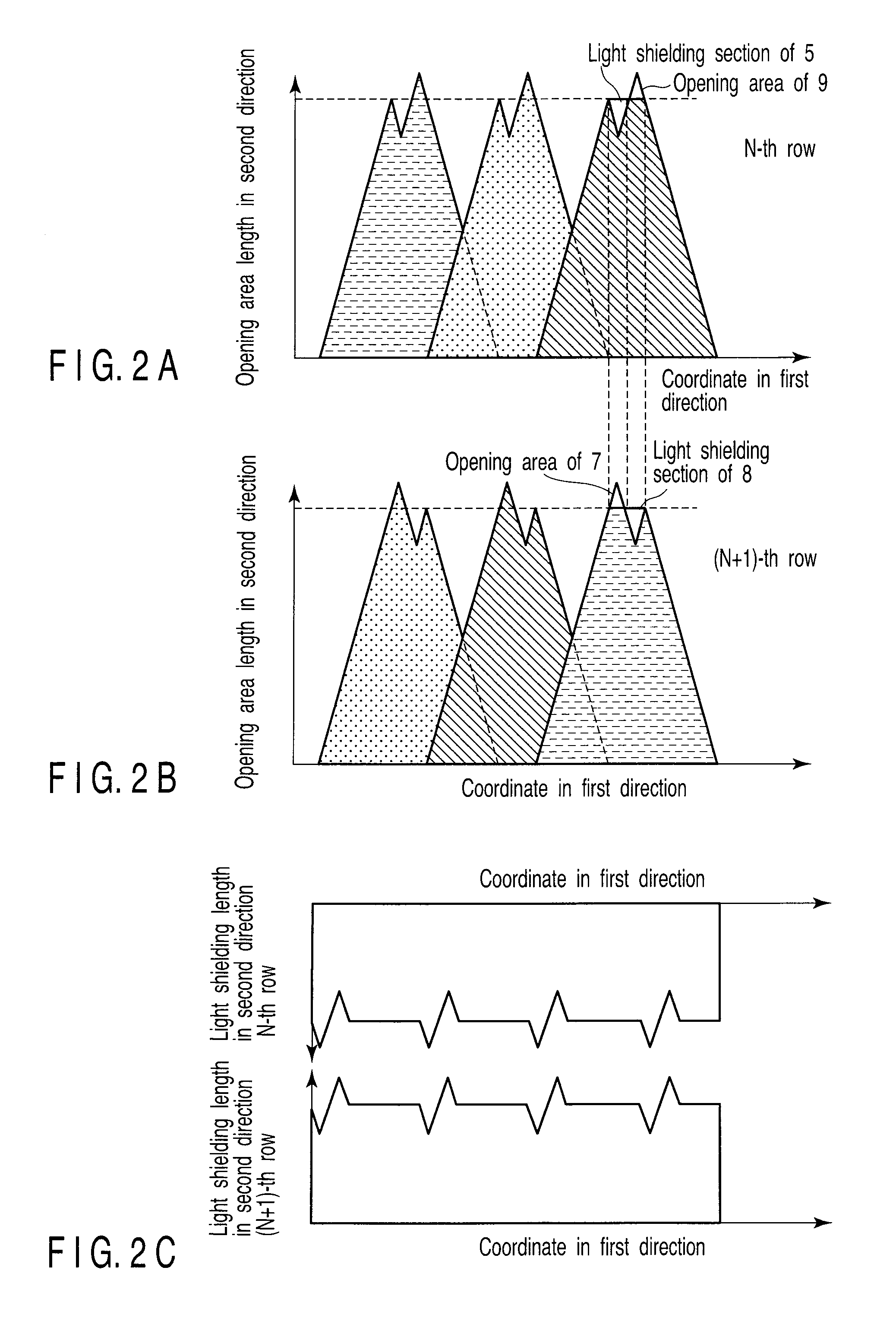
If it is attempted to satisfy this condition while providing the structure in which coordinate points in the first direction having TFTs, Cs lines, and shielding of poor orientation of liquid crystals are locally present, dummy the light shielding sections which are normally unnecessary must be provided such that the opening area length in the second direction becomes constant in the first direction in addition to the light shielding sections which are originally necessary, thereby posing a problem that the numerical aperture is lowered.

Method used


Image

  • Three-dimensional image display apparatus for displaying three-dimensional image
  • Three-dimensional image display apparatus for displaying three-dimensional image
  • Three-dimensional image display apparatus for displaying three-dimensional image

Examples


Embodiment Construction

[0049]A three-dimensional image display apparatus according to an embodiment of the present invention will be described below in detail with referring to the accompanying drawings.

[0050]FIG. 1 is an enlarged view schematically showing a part of a display section for displaying a flat image in the three-dimensional image display apparatus according to the embodiment of the present invention in an enlarging manner.

[0051]This display section is constituted of sub-pixels 10 arranged in a matrix form in the horizontal and vertical directions, and a color filter segment 12 is provided in front of the sub-pixel 10. Further, the sub-pixel 10 is constituted of light shielding sections or shielding areas 3 and 6, and picture elements partitioned by the light shielding sections 3 and 6, and an opening area or part 1 is determined by the partitioned picture element and the color filter segment 12 corresponding to the sub-pixel 10. White light emitted from a backlight (not shown) is transmitted ...


PUM


Abstract

In an apparatus for displaying a three-dimensional image, sub-pixels having color components are arranged in a longitudinal direction and in a lateral direction in a matrix form, in a display section for displaying a flat image, and a light ray control element is disposed so as to be opposed to the display section. In the light ray control element, linear optical openings extending in a vertical direction are arranged in the lateral direction. A sum of opening area lengths of opening areas of a plurality of sub-pixels adjacent to each other in a horizontal direction is varied in a single row, and the sum thereof in a plurality of rows becomes constant. Further, an arrangement of the sub-pixels is a color arrangement of a mosaic arrangement or a lateral stripe arrangement.

Description

CROSS-REFERENCE TO RELATED APPLICATIONS[0001]This is a Continuation Application of PCT Application No. PCT / JP2008 / 055185, filed Mar. 14, 2008, which was published under PCT Article 21(2) in English.[0002]This application is based upon and claims the benefit of priority from prior Japanese Patent Application No. 2007-089530, filed Mar. 29, 2007, the entire contents of which are incorporated herein by reference.BACKGROUND OF THE INVENTION[0003]1. Field of the Invention[0004]The present invention relates to a three-dimensional image display apparatus for displaying a three-dimensional image.[0005]2. Description of the Related Art[0006]As a three-dimensional image display apparatus capable of displaying an animation, i.e., a so-called three-dimensional display, various types are known. In recent years, a system of a flat panel type and requiring no dedicated spectacles or the like is strongly demanded. As a three-dimensional image display apparatus of the type that requires no dedicated...

Claims


Application Information

Patent Timeline
IPC IPC(8): G09G5/00G02B30/27
CPCG02B27/2214G02F1/133512G02F2201/52H04N13/0445H04N13/0415H04N13/0422H04N13/0404H04N13/305H04N13/324H04N13/349H04N13/317G02B30/27G02F1/1343G02B30/00
Inventor FUKUSHIMA, RIEKOHIRAYAMA, YUZOTAIRA, KAZUKISAISHU, TATSUO
Owner KK TOSHIBA
Why Eureka
Eureka Blog
Learn More