Multipurpose Antenna Configuration for a Contactless Data Carrier

a data carrier and multi-purpose technology, applied in the field of antenna configuration, to achieve the effect of improving data carrier and antenna configuration

Inactive Publication Date: 2009-01-01
NXP BV
View PDF6 Cites 8 Cited by
  • Summary
  • Abstract
  • Description
  • Claims
  • Application Information

AI Technical Summary

Benefits of technology

[0004]The invention has for its object to eliminate the problems mentioned above and to provide an improved antenna configuration and an improved data carrier.

Problems solved by technology

Owing to the wide opening angle, the central longitudinal portions of the two antenna arms are at a comparatively large distance from one another, except for the region of their first ends, which is indeed favorable for a good decoupling of the two antenna arms, but which also has disadvantages that have manifested themselves in tests carried out at applicant's.
A limitation and disadvantages are accordingly present in the known antenna configuration and the known data carrier, because a large opening angle is present between the antenna arms, and the antenna configuration is constructed and suitable only for an electrical coupling and accordingly for an operational co-operation with only a single integrated component.

Method used


Image

  • Multipurpose Antenna Configuration for a Contactless Data Carrier
  • Multipurpose Antenna Configuration for a Contactless Data Carrier
  • Multipurpose Antenna Configuration for a Contactless Data Carrier

Examples


Embodiment Construction

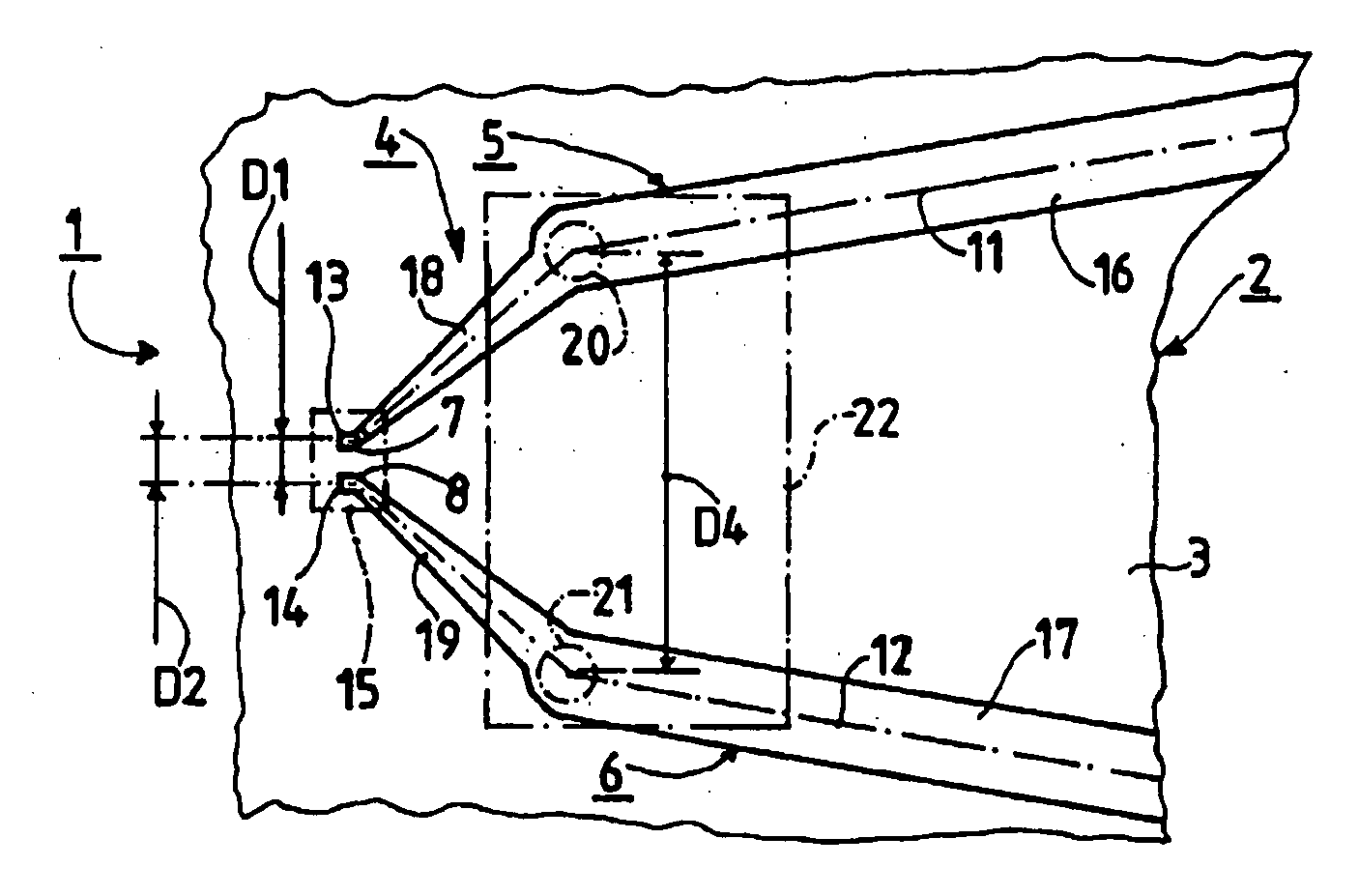
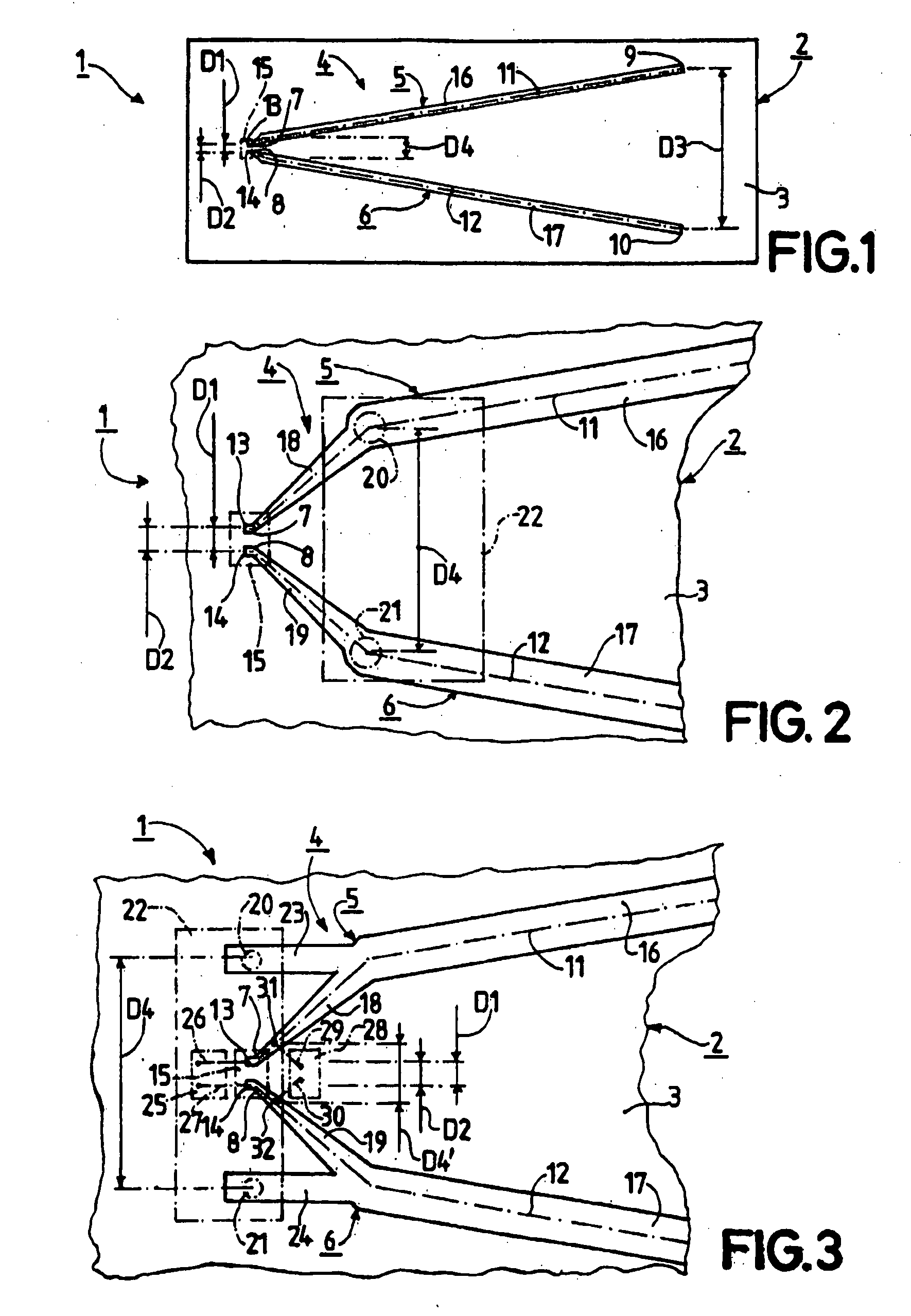
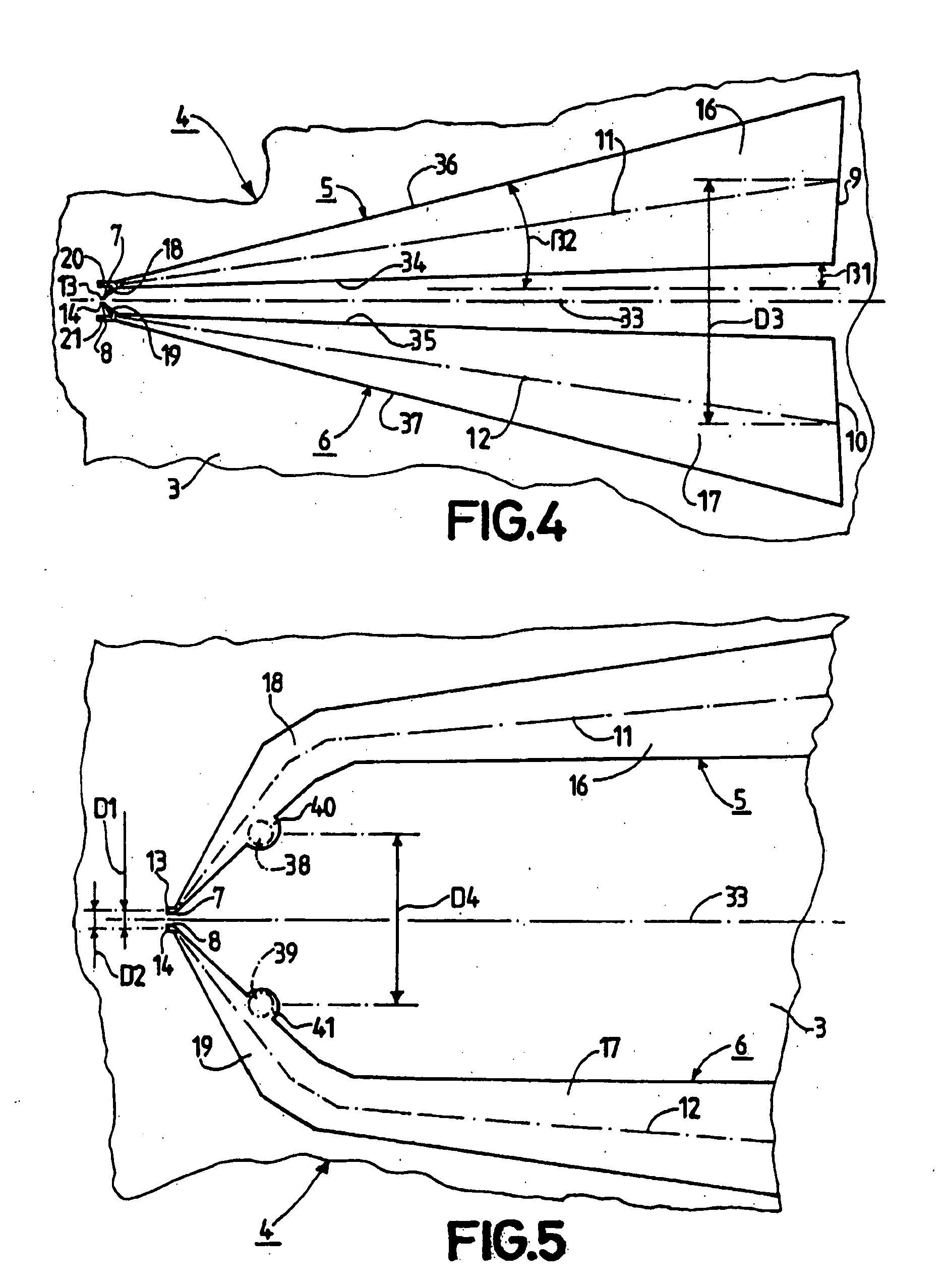
[0023]FIG. 1 shows a data carrier 1, which constitutes a so-termed label or a so-termed tag. Such a data carrier may alternatively be constructed as a contactless chip card. The data carrier 1 is provided and constructed for achieving contactless communication with a communication station (not shown). The data carrier 1 comprises a data carrier body 2. The data carrier body 2 in the present case consists of two synthetic resin foils that have been interconnected in a lamination process. Only one of these two foils, however, of the data carrier body 2 is shown in FIGS. 1 and 2. This one foil forms a carrier 3, which serves to support an antenna configuration 4 of the data carrier 1. The data carrier body 2 may alternatively be formed from a different dielectric material, for example from paper or a PC-board material. The contactless communication with a communication station as mentioned above can be carried out by means of the antenna configuration 4, which communication involves bo...


PUM


Abstract

In an antenna configuration (4) with two antenna arms (5, 6) arranged in a V-shape, two coupling zones (13, 14) for electrically coupling to respective terminals of an integrated component (15) are provided in the region of the ends (7, 8) of the antenna arms (5, 6) lying close together, wherein each of the two antenna arms (5, 6) in addition comprises a coupling region (20, 21) at a distance from its coupling zone (13, 14), and each coupling region (20, 21) is designed for electrically coupling to a terminal of a further electronic component (22).

Description

FIELD OF THE INVENTION[0001]The invention relates to an antenna configuration, which comprises a carrier for carrying antenna arms of the antenna configuration, and which comprises a first antenna arm and a second antenna arm, wherein each of the two antenna arms is connected to the carrier and is formed from an electrically conductive material and comprises a first end and a second end and a central longitudinal portion extending from the first end to the second end, and wherein said two central longitudinal portions are at a first distance from one another at the two first ends, and each of the two first ends has a coupling zone for electrically coupling to a terminal of an integrated component, which two coupling zones are at a second distance from one another, while said integrated component is designed for communicating in a contactless manner, and wherein said two central longitudinal portions are at a third distance from one another at the two second ends, which third distanc...

Claims


Application Information

Patent Timeline
Patent Type & Authority Applications(United States)
IPC IPC(8): H01Q9/06
CPCG06K19/07749G06K19/07786H01Q9/28H01Q1/2225H01Q9/26H01Q1/22
Inventor HILGERS, ACHIM
Owner NXP BV
Why Eureka
Try Eureka