
Multi-Band Antenna Device For Radio Communication Terminal And Radio Communication Terminal Comprising The Multi-Band Antenna Device

a multi-band antenna and radio communication terminal technology, applied in the structure of radiating elements, elongated active elements, resonance antennas, etc., can solve the problems of reducing directivity, undesirable modification, and limiting the height of pifa antennas, and achieves good performance, wide bandwidth, and high efficiency.

Active Publication Date: 2009-01-01
SONY CORP
View PDF4 Cites 30 Cited by
  • Summary
  • Abstract
  • Description
  • Claims
  • Application Information

AI Technical Summary

Benefits of technology

The present invention provides a multi-band antenna device for a radio communication terminal that can operate at multiple frequency bands with high efficiency. The antenna has a wide bandwidth and can be used in various radio communication terminals, such as mobile phones. The antenna has a simple structure and minimal contacts, and can be easily integrated into the radio communication terminal. The technical effects of the invention include improved bandwidth, high efficiency, and reduced impedance shift in multiple operating positions. The invention also provides a method for tuning the multi-band antenna device.

Problems solved by technology

The height of the PIFA antennas is often a limiting factor for decreasing the size of the mobile communication terminal.
This, however, is an undesirable modification as the height increase makes the antenna unattractive for small communication devices and may reduce directivity.
However, prior art antenna designs will still be a limiting factor when developing radio terminals with adequate bandwidth to cover, for example, all of the DCS, PCS and UMTS frequency bands, at the same time recognizing the desire to provide compact terminals.
However, both GSM and EGSM (EGSM is an acronym for Extended Global System for Mobile communications-Extended GSM) are generally not achievable by the prior art antenna solutions fulfilling the above mentioned spatial requirements, i.e. known antennas of the discussed type are not capable of operating efficiently in both the GSM 850 MHz and the EGSM 900 MHz bands.
This planar requirement restrains the design possibilities of the radiating element, which must be oriented in the same plane as the ground substrate, i.e. the antenna is limited to flat, planar implementations.
However, this antenna system is not related to compact built-in antennas devised to be incorporated into mobile or portable radio communication terminal.
Other known solutions are variable pitch meanders have been used in the past on stub antennas to achieve dual-band performance, but are generally difficult to tune and cannot be used more generally in PIFA configurations.
However, ½ wave elements for the 1800 band were up to now not implemented due to the space requirements.
A more general problem with known built-in antennas is not only small bandwidth, but also significantly worse gain performance than a traditional external antenna i.e. some kind of stub antenna.
Furthermore electrical contacts are expensive, at least with regard to mass produced products, such as mobile communication terminals.

Method used


Image

  • Multi-Band Antenna Device For Radio Communication Terminal And Radio Communication Terminal Comprising The Multi-Band Antenna Device
  • Multi-Band Antenna Device For Radio Communication Terminal And Radio Communication Terminal Comprising The Multi-Band Antenna Device
  • Multi-Band Antenna Device For Radio Communication Terminal And Radio Communication Terminal Comprising The Multi-Band Antenna Device

Examples


Embodiment Construction

[0071]It will be understood that the Figures, illustrating embodiment of the invention, are merely schematic and are not drawn to scale. For clarity of illustration, certain dimensions may have been exaggerated while other dimensions may have been reduced. Also, where appropriate, the same reference numerals and letters are used throughout the Figures to indicate the same parts and dimensions.

[0072]The following description focuses on embodiment of the present invention applicable to a mobile telephone. However, it will be appreciated that the invention is not limited to this application but may be applied to many other mobile communication terminals in which to implement a radio antenna design according to the present invention, including the following examples. The terms mobile or radio communication terminal comprises all mobile equipment devised for radio communication with a radio station, which radio station also may be mobile terminal or e.g. a stationary base station. Conseq...


PUM


Abstract

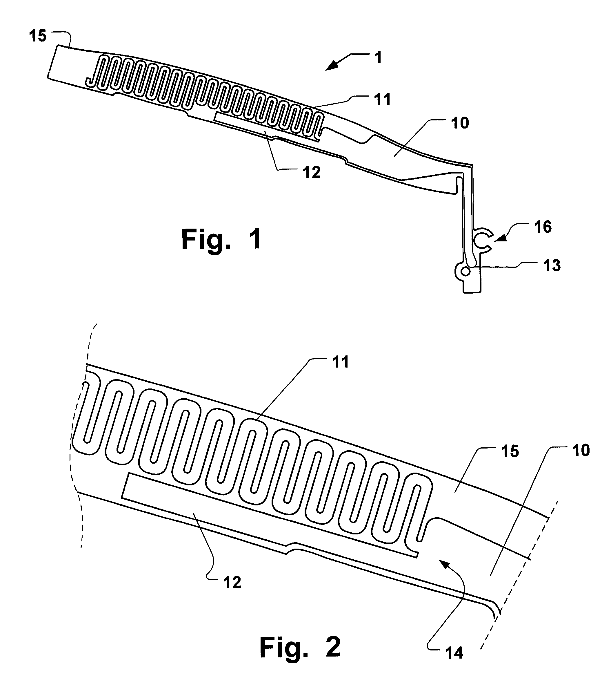
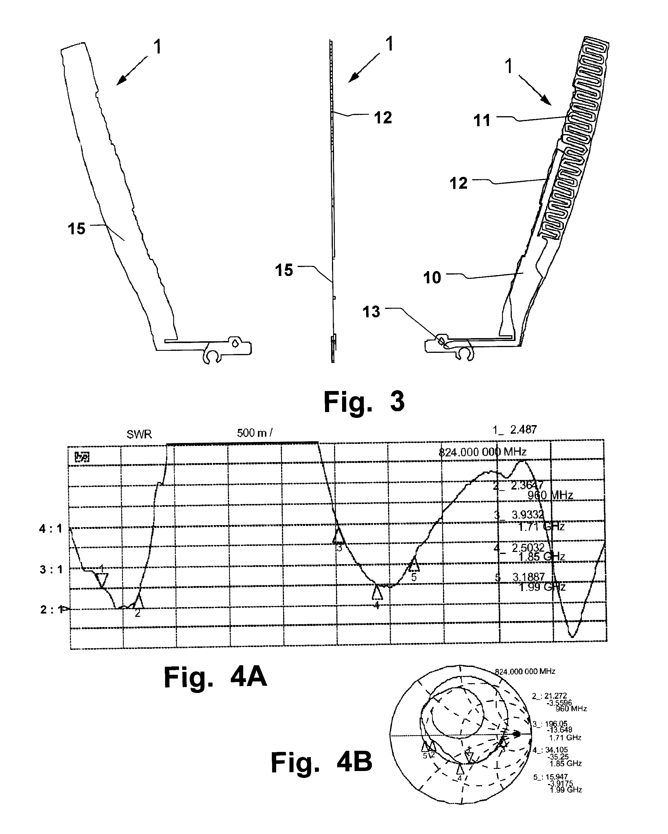
A multi-band radio antenna device (1) for a radio communication terminal is disclosed. The antenna device comprises a substrate and a radiating antenna element thereon having a radio signal feeding point (13), wherein the radiating element comprises a continuous trace of conductive material. The continuous trace has a first radiating portion connected to said radio signal feeding point comprising a at least partly meandered radiating portion (11) arranged distal from said radio signal feeding point (13) and connected to an elongate radiating portion (10) arranged proximal to and connected to said signal feeding point, and a second radiating portion (12) connected as a branch to said first radiating portion at a branching position (14) thereof arranged distal from said radio signal feeding point (13). The antenna device offers a minimized number of necessary contacts and improved antenna efficiency.

Description

FIELD OF THE INVENTION[0001]This invention pertains in general to the field of antennas for radio communication terminals and, in particular, to compact built-in antennas devised to be incorporated into mobile or portable radio communication terminals and having a wide bandwidth to facilitate operation of such terminals within multiple frequency bands. Furthermore, the invention pertains to a method of tuning such an antenna and a manufacturing process for an antenna.BACKGROUND OF THE INVENTION[0002]The use of radio communication networks is rapidly becoming a part of the daily life for more and more people around the globe. For instance, the GSM (Global System for Mobile Communications) networks offer a variety of functions. Generally, radio communication systems based on such networks use radio signals transmitted by a base station in the downlink over the traffic and control channels are received by mobile or portable radio communication terminals, each of which have at least one...

Claims


Application Information

Patent Timeline
Patent Type & Authority Applications(United States)
IPC IPC(8): H01Q1/24H01Q1/38
CPCH01Q1/243H01Q1/36H01Q21/30H01Q9/40H01Q9/42H01Q1/38
Inventor DAHLSTROM, ANDERSVANCE, SCOTT
Owner SONY CORP
Learn More