
Direct torque actuator control for control moment gyroscope

a technology of actuator control and control moment, which is applied in the direction of vehicle position/course/altitude control, process and machine control, instruments, etc., to achieve the effect of improving the responsiveness of the control moment gyroscop

Inactive Publication Date: 2009-01-01
ITHACO SPACE SYST
View PDF10 Cites 18 Cited by
  • Summary
  • Abstract
  • Description
  • Claims
  • Application Information

AI Technical Summary

Benefits of technology

[0006]The subject technology provides a more suitable solution to improve the responsiveness of a control moment gyroscope and, in turn, an attitude control system using the same.
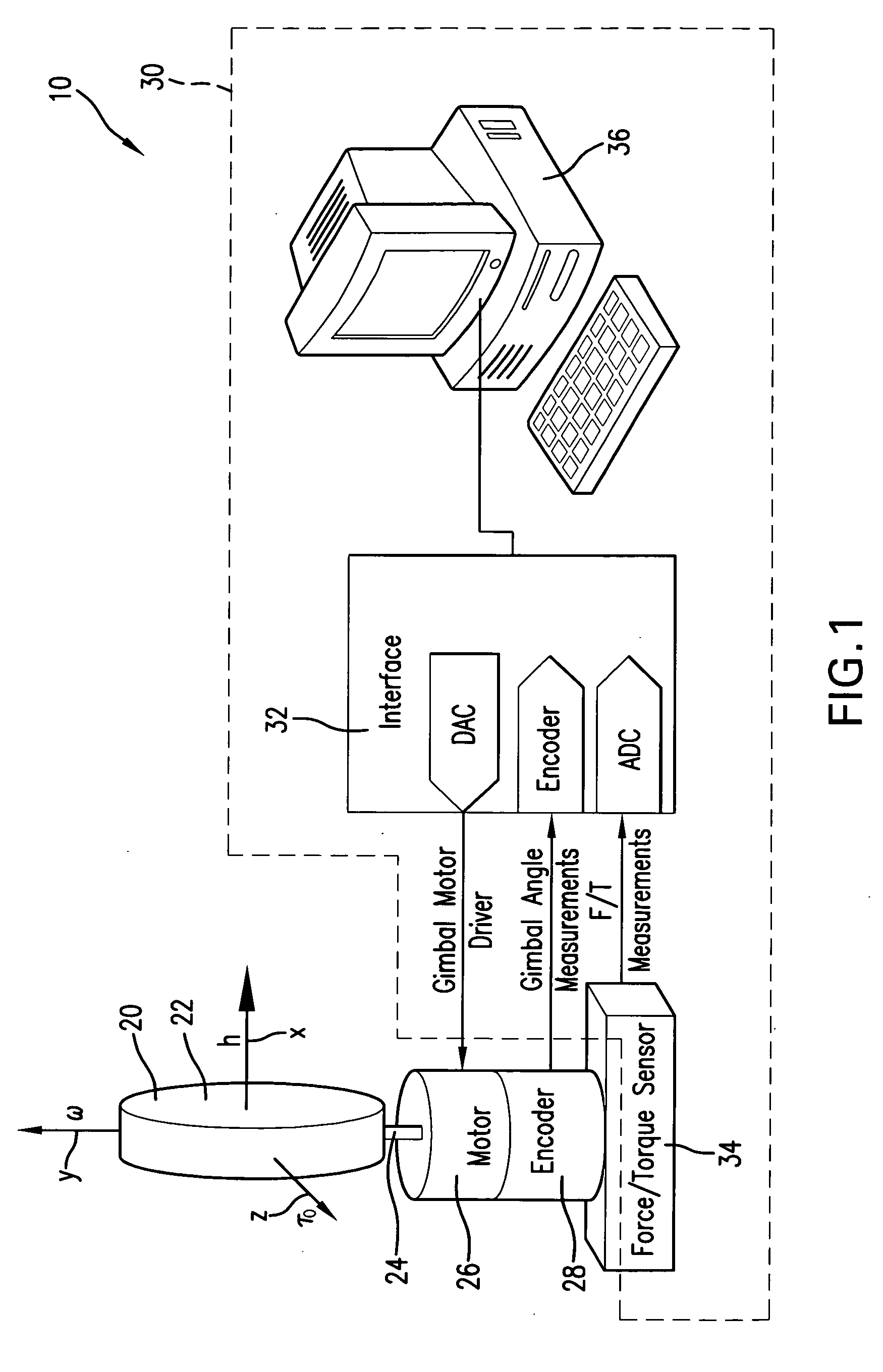
[0011]The subject technology also may alleviate the need to precisely measure the gimbal spin rate. Only gimbal angle and the torque measurements are required, and the gimbal angle information is used simply to align the torque measurement mathematically with the output axis. As a result, the control system can be reduced to a single-input, single-output problem.

Problems solved by technology

However, because the control moment gyroscope's gimbal torque determines the rate of change in this output torque, the feedback control can be based on an unconditionally stable (i.e., 90° phase margin, infinite gain margin) feedback of output torque error to gimbal input torque.

Method used


Image

  • Direct torque actuator control for control moment gyroscope
  • Direct torque actuator control for control moment gyroscope
  • Direct torque actuator control for control moment gyroscope

Examples


Embodiment Construction

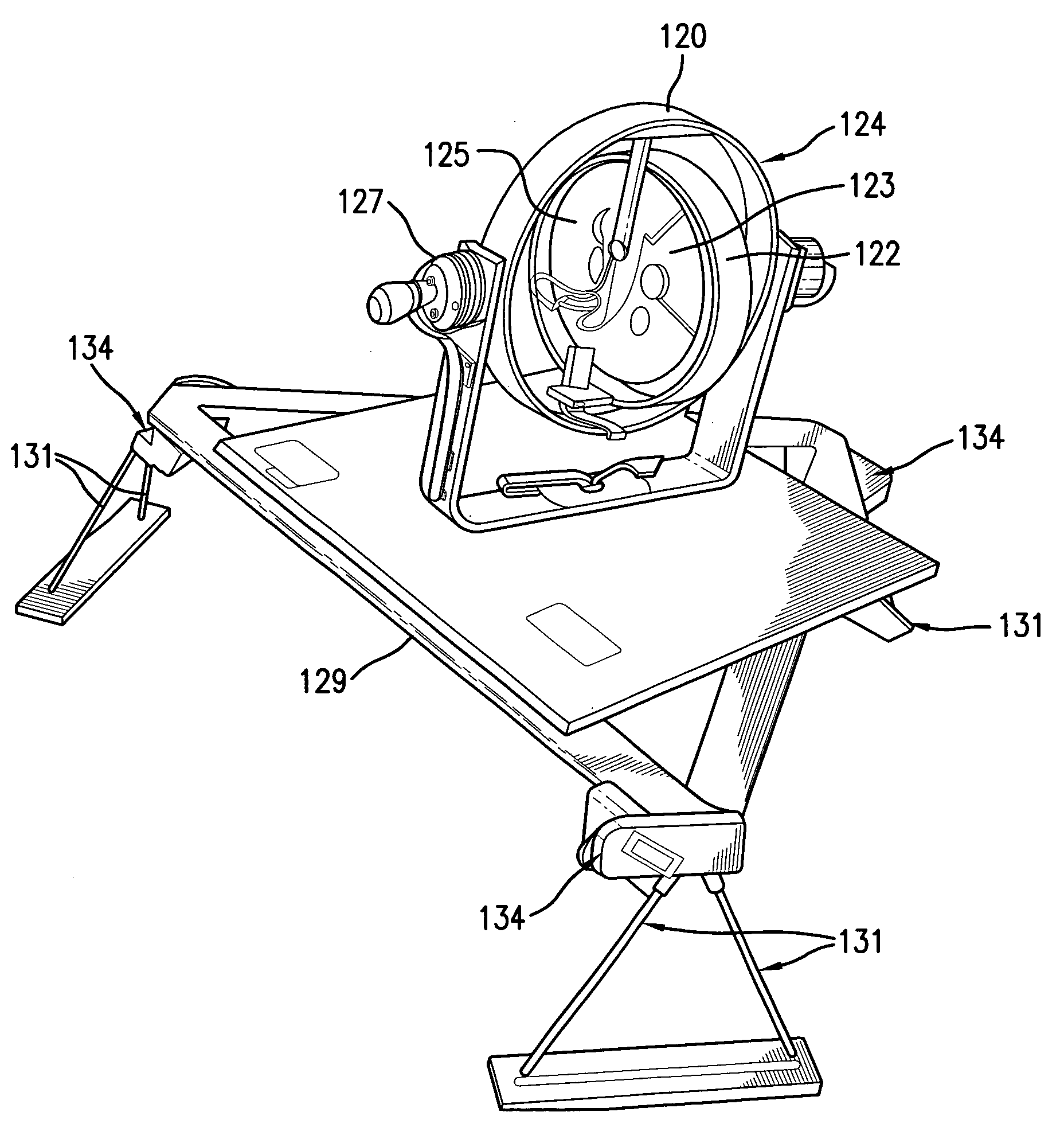
[0023]The present invention overcomes many of the prior art problems associated with control moment gyroscopes. The advantages, and other features of the control moment gyroscopes disclosed herein, will become more readily apparent to those having ordinary skill in the art from the following detailed description of certain embodiments taken in conjunction with the drawings which set forth representative embodiments of the present invention and wherein like reference numerals identify similar structural elements.

[0024]Unless otherwise specified, the illustrated embodiments can be understood as providing exemplary features of varying detail of certain embodiments, and therefore, unless otherwise specified, features, components, modules, elements, and / or aspects of the illustrations can be otherwise combined, interconnected, sequenced, separated, interchanged, positioned, and / or rearranged without materially departing from the disclosed systems or methods. Additionally, the shapes and ...


PUM


Abstract

A control moment gyroscope system for delivering a target torque to a spacecraft including a rotor assembly having a rotor and a motor to spin the rotor about a rotor axis. A gimbal assembly has a gimbal for supporting the rotor assembly and a gimbal torque motor to rotate the gimbal about a gimbal axis, which is normal to the rotor axis, to generate an output torque. A control system has a sensor for determining the output torque and a processor in communication with the rotor assembly, the gimbal assembly and the sensor. The processor requests the target torque and establishes a feedback control loop to generate a torque error signal based on the output torque for bringing the output torque within a predetermined range of the target torque.

Description

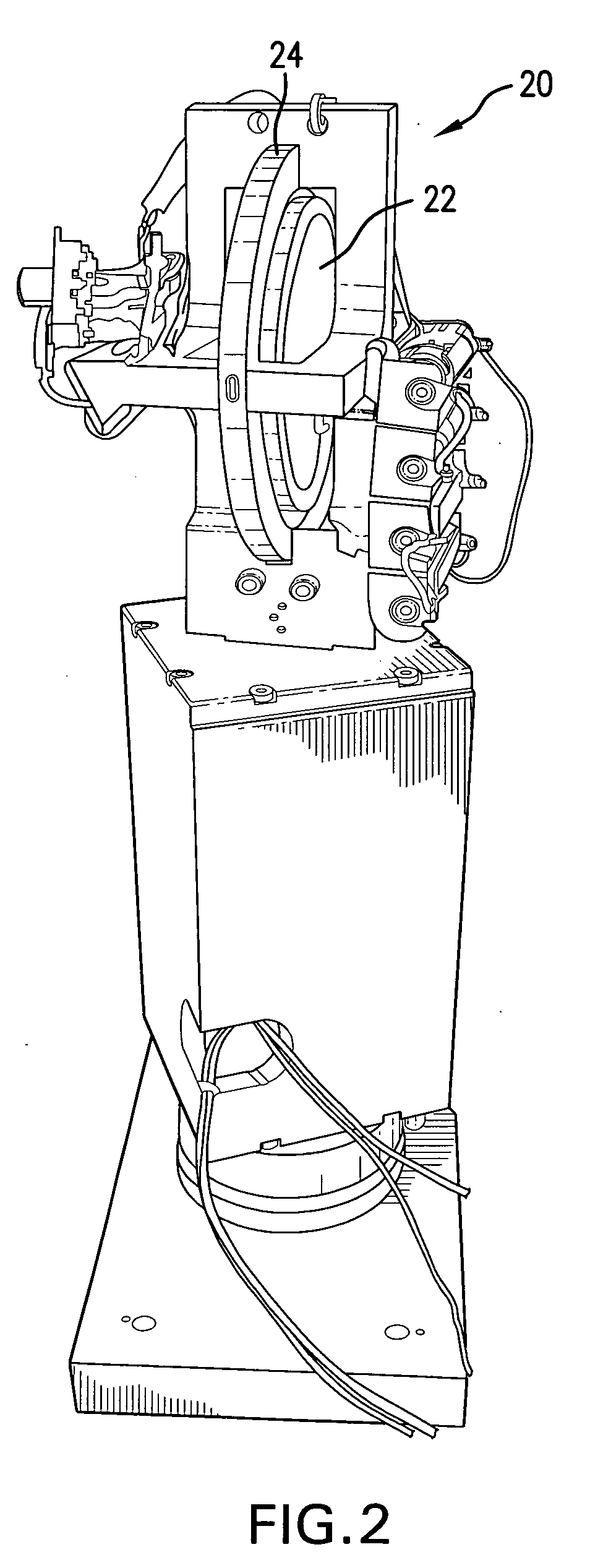
CROSS-REFERENCE TO RELATED APPLICATION[0001]This application claims priority to U.S. Provisional Patent Application No. 60 / 925,073, filed Apr. 18, 2007, which is incorporated herein by reference.BACKGROUND OF THE INVENTION[0002]Control moment gyroscopes (CMGs) are well known means of providing directional control of spacecraft. One example is described in U.S. Pat. No. 5,386,738 to Havenhill, the disclosure of which is incorporated herein by reference in its entirety. CMGs typically include a rotor, a motor to spin the rotor about a rotor axis, a gimbal, a gimbal torque motor to rotate the gimbal about a gimbal axis and a control system. The control moment gyroscope is mounted within the spacecraft along the axis in which torque will be induced. The rotor is mechanically supported in the gimbal and is rotated about the gimbal axis, which is normal to the rotor axis.[0003]During operation of the CMG, the rotor is spun about its rotor axis by a motor at a predetermined rate. In order ...

Claims


Application Information

Patent Timeline
IPC IPC(8): B64G1/36
CPCY10T74/1254B64G1/286
Inventor PECK, MASONBIALKE, WILLIAM E.
Owner ITHACO SPACE SYST
Learn More