Wind Noise Reduction Device
a wind noise reduction and wind noise technology, applied in the direction of transducer casings/cabinets/supports, electrical transducers, frequency response correction, etc., can solve the problems of distorted sound, difficult to fit the integrated microphone with a mechanical wind-shielding device, and sound signal corruption with wind nois
- Summary
- Abstract
- Description
- Claims
- Application Information
AI Technical Summary
Benefits of technology
Problems solved by technology
Method used
Image

Examples
embodiment 1
[0066]A first embodiment of the invention will be described below. Described first are the features common to, or referred to in the course of the description of, Examples 1 to 5 presented later in connection with the first embodiment.
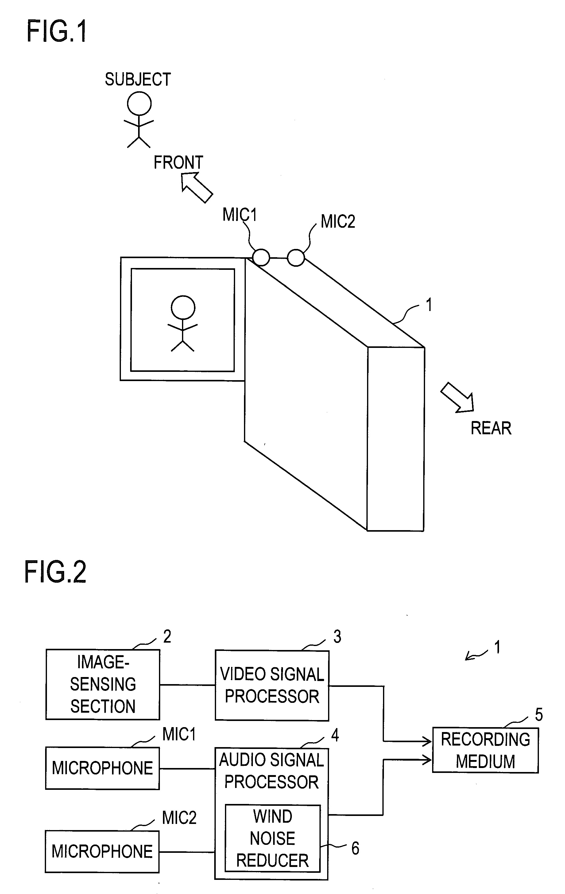
[0067]FIG. 1 is a perspective exterior view of an image-sensing apparatus 1 according to the first embodiment of the invention. The image-sensing apparatus 1 is a digital video camera capable of recording sound as well. The image-sensing apparatus 1 is provided with a microphone MIC1 in a left part of its main casing, and with a microphone MIC2 in a right part of its main casing. The microphone MIC1 collects sound coming from the left side of the image-sensing apparatus 1, and the microphone MIC2 collects sound coming from the right side of the image-sensing apparatus 1; thus together the microphones MIC1 and MIC2 constitute a stereo (stereophonic, or binaural) microphone. As an arrangement of the microphones MIC1 and MIC2 different from that shown in ...
example 1
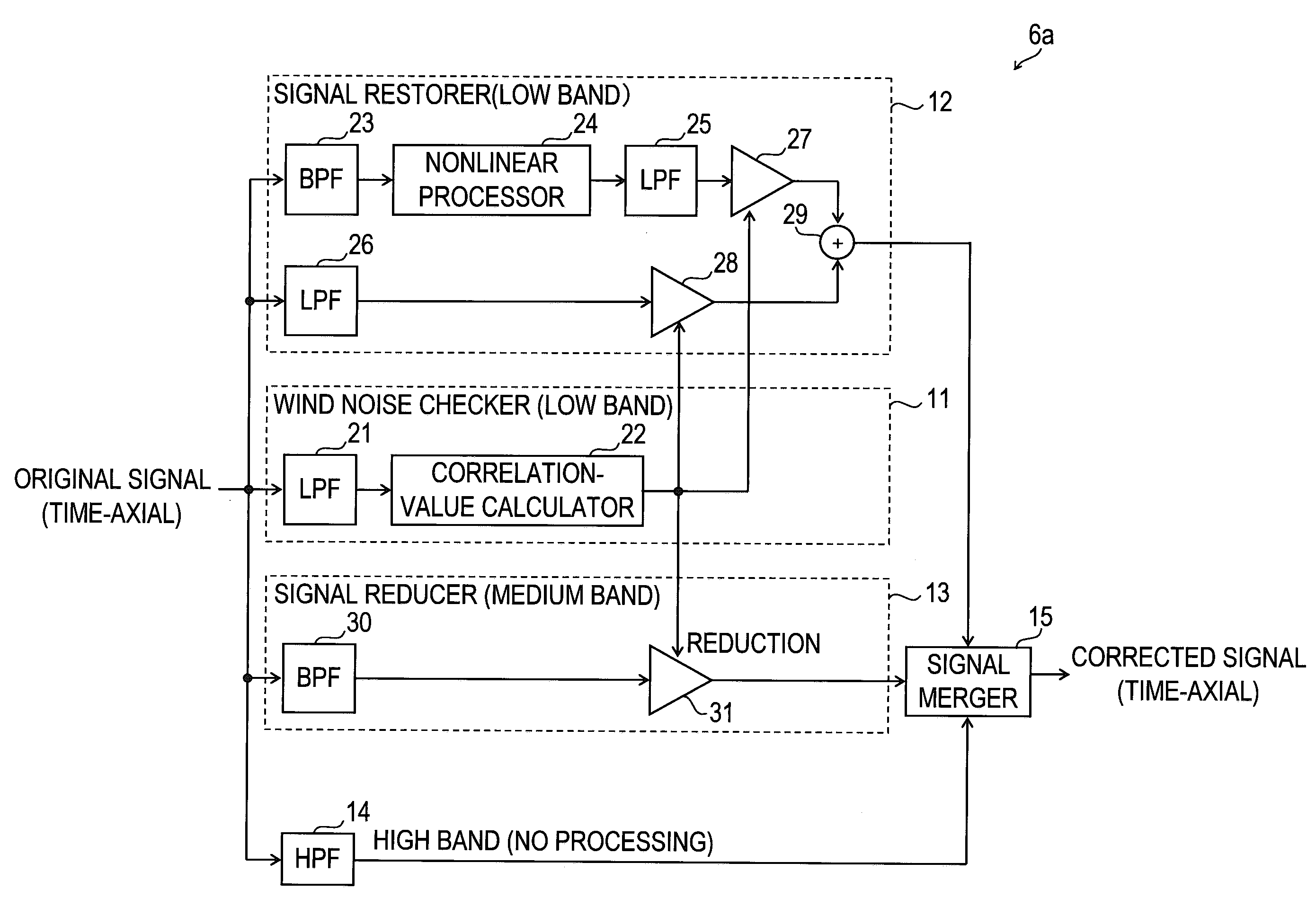
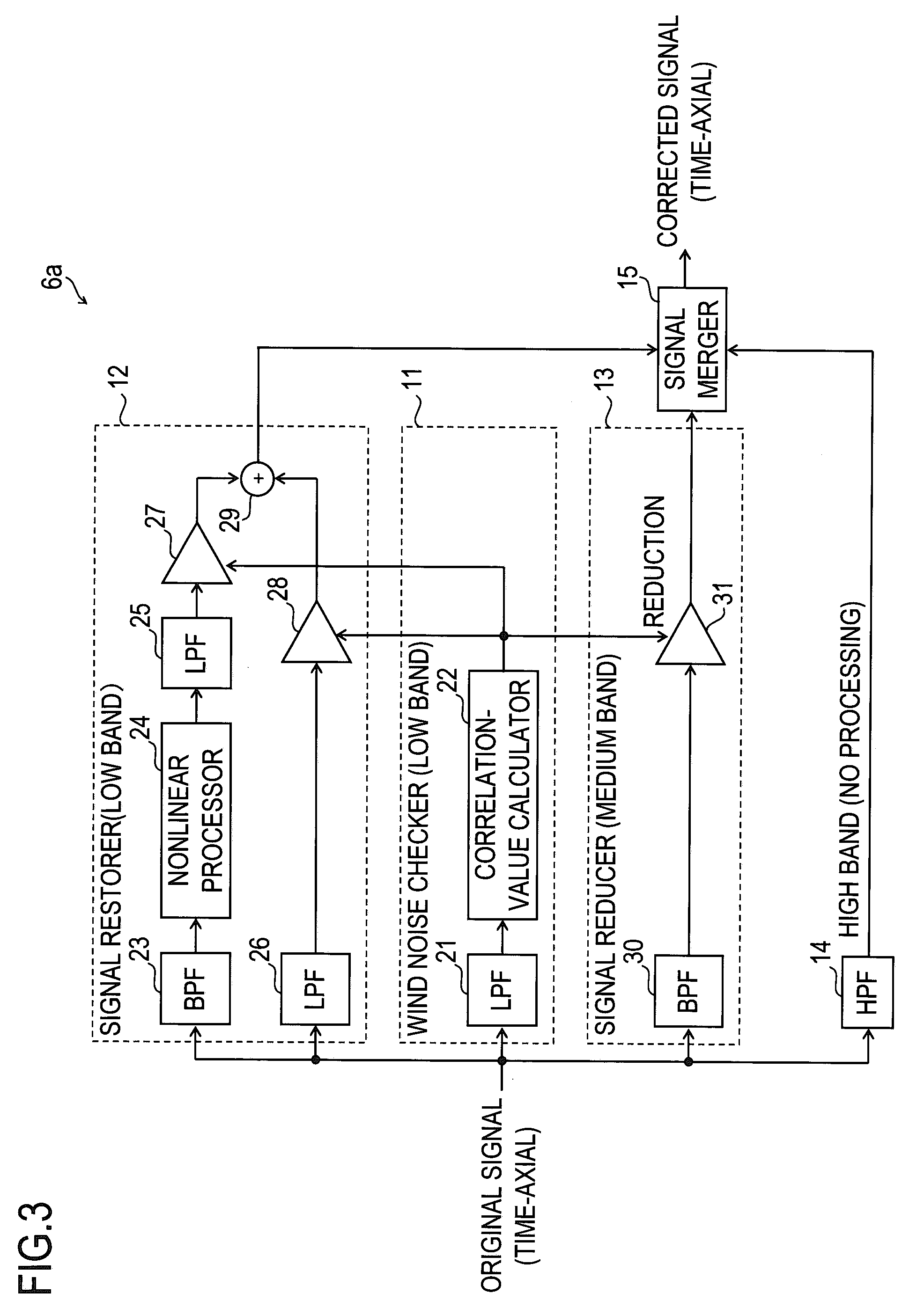
[0083]First, Example 1 will be described. In Example 1, both signal restoration processing and signal reduction processing are performed on the time axis.
[0084]FIG. 3 is an internal block diagram of the wind noise reducer 6a in Example 1. The wind noise reducer 6a is used as the wind noise reducer 6 in FIG. 2. The wind noise reducer 6a comprises portions referred to by the reference signs 11 to 15.
[0085]The input signal (input sound signal) to the wind noise reducer 6a is a sound signal on the time axis (in other words, a sound signal expressed in terms of time regions; hereinafter “time-axial signal”) composed of a plurality of channel signals. Specifically, the audio signal processor 4 in FIG. 2 converts, at a predetermined sampling frequency, the analog output signals from the microphones MIC1 and MIC2 into digital signals. Here, the channel signal in which the digital signals corresponding to the output signal from the microphone MIC1 are arranged chronologically is represented ...
example 2
[0144]Next, Example 2 will be described. In Example 2, both signal restoration processing and signal reduction processing are performed on the frequency axis.
[0145]FIG. 5 is an internal block diagram of the wind noise reducer 6b in Example 2. The wind noise reducer 6b is used as the wind noise reducer 6 in FIG. 2. The wind noise reducer 6b comprises: a correlation-value calculator 51 functioning as a wind noise checker for the low band; a wind noise checker 52 for the medium band; a signal reducer 53, a signal restorer 54; and a signal merger 55. The wind noise checker 52 comprises n correlation-value calculators 52_1, 52_2, . . . , 52—n, and the signal reducer 53 comprises n multipliers 53_1, 53_2, . . . , 53—n (where n is an integer of 2 or more). The signal restorer 54 comprises a restored signal generator 61 and a signal selector 62.
[0146]The input signal (input sound signal) to the wind noise reducer 6b is a sound signal on a frequency axis (in other words, a sound signal expre...
PUM
 Abstract
Description
Claims
Application Information
 - R&D
- Intellectual Property
- Life Sciences
- Materials
- Tech Scout
- Unparalleled Data Quality
- Higher Quality Content
- 60% Fewer Hallucinations
Browse by: Latest US Patents, China's latest patents, Technical Efficacy Thesaurus, Application Domain, Technology Topic, Popular Technical Reports.
© 2025 PatSnap. All rights reserved.Legal|Privacy policy|Modern Slavery Act Transparency Statement|Sitemap|About US| Contact US: help@patsnap.com