
Combined optical and electrical transmission assembly and module

Inactive Publication Date: 2008-12-18
HITACHI CABLE
View PDF39 Cites 160 Cited by
  • Summary
  • Abstract
  • Description
  • Claims
  • Application Information

AI Technical Summary

Benefits of technology

[0048]According to one embodiment of the invention, because arranging on the film type optical waveguide wiring the electrical-to-optical conversion unit and / or optical-to-electrical conversion unit requiring very high positional accuracy makes rigid substrate fabrication accuracy as good as on the order of a few tens of μm, it is possible to use the inexpensive rigid substrate, and facilitate making cost low.
[0049]Further, making the power cable shorter than the electrical cable allows inadvertent pulling force to be applied to the power cable, and prevented from being applied to the electrical cable. This prevents the electrical cable from slipping out of the external device by inadvertent pulling force.

Problems solved by technology

As high-speed transmission lines, there are used coaxial cables having a shield function, or differential transmission lines comprising a pair of differential lines in a shield, but their transmission distance is limited because of problems of noise or skew.
To separately supply power for driving the IC, exclusive cables or connectors are separately required, which also complicates construction, causing problems with handling and cost.
Mounting those with different mounting accuracy on the same substrate requires matching to the strictest mounting accuracy specifications, which makes it difficult to fabricate the substrate, and makes the substrate costly.
Further, the high-speed electrical IF connector is not assumed to be used in optical connection, and its connection strength is weaker than that of a typical optical IF connector.
This causes the problem that when the connector is pulled, the connector tends to slip out of a connector of the external device, which may cause an abrupt voltage change in the optical device, leading to a breakdown of the optical device.

Method used


Image

  • Combined optical and electrical transmission assembly and module
  • Combined optical and electrical transmission assembly and module
  • Combined optical and electrical transmission assembly and module

Examples


Embodiment Construction

[0065]Giving an outline of the invention, the invention relates to a combined optical and electrical transmission assembly and module, which combines and transmits light and electricity, and particularly to a low-cost and high-reliability combined optical and electrical transmission module.

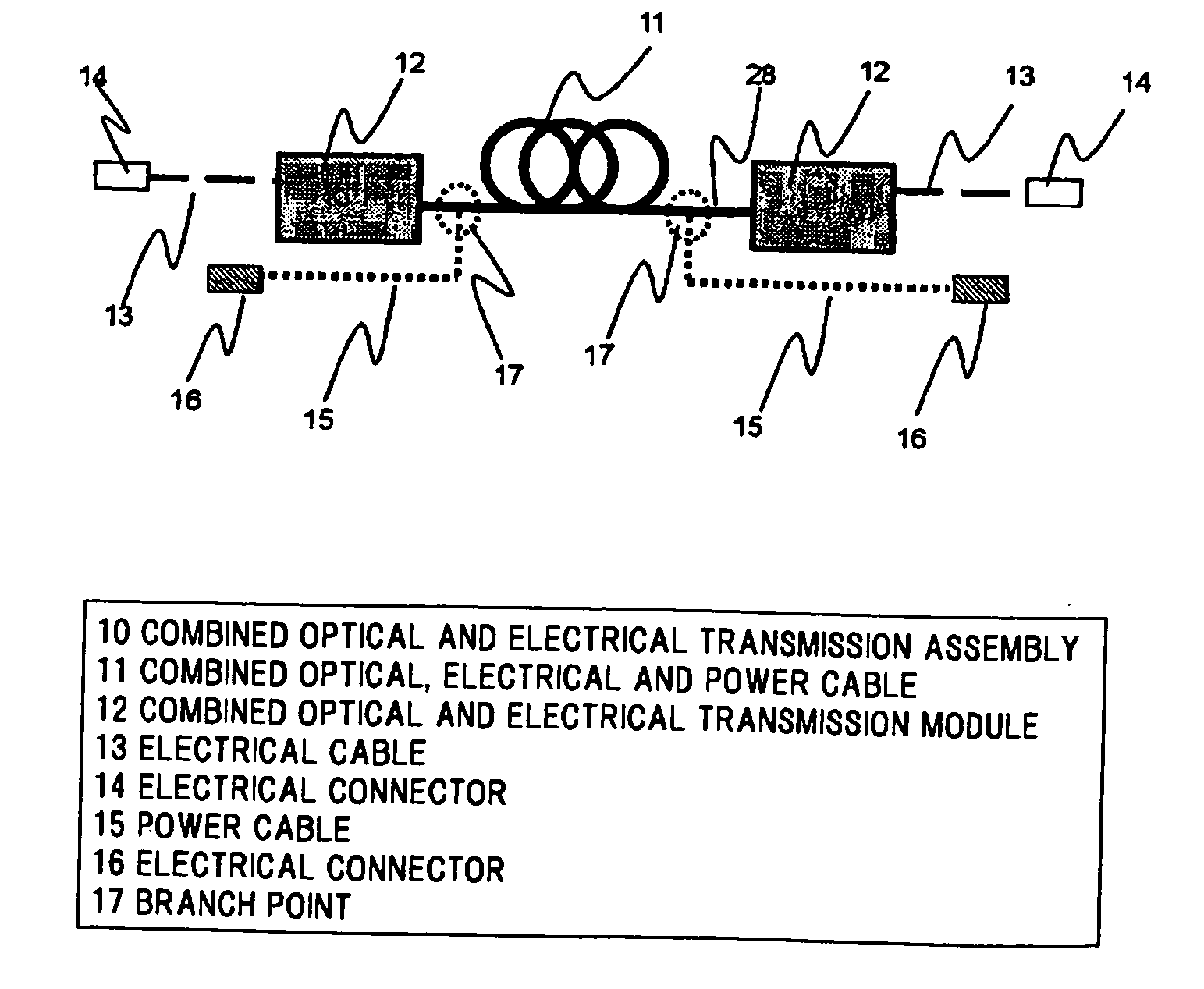
[0066]First, shown in FIGS. 1A to 1C is the entire structure of a combined optical and electrical transmission assembly.

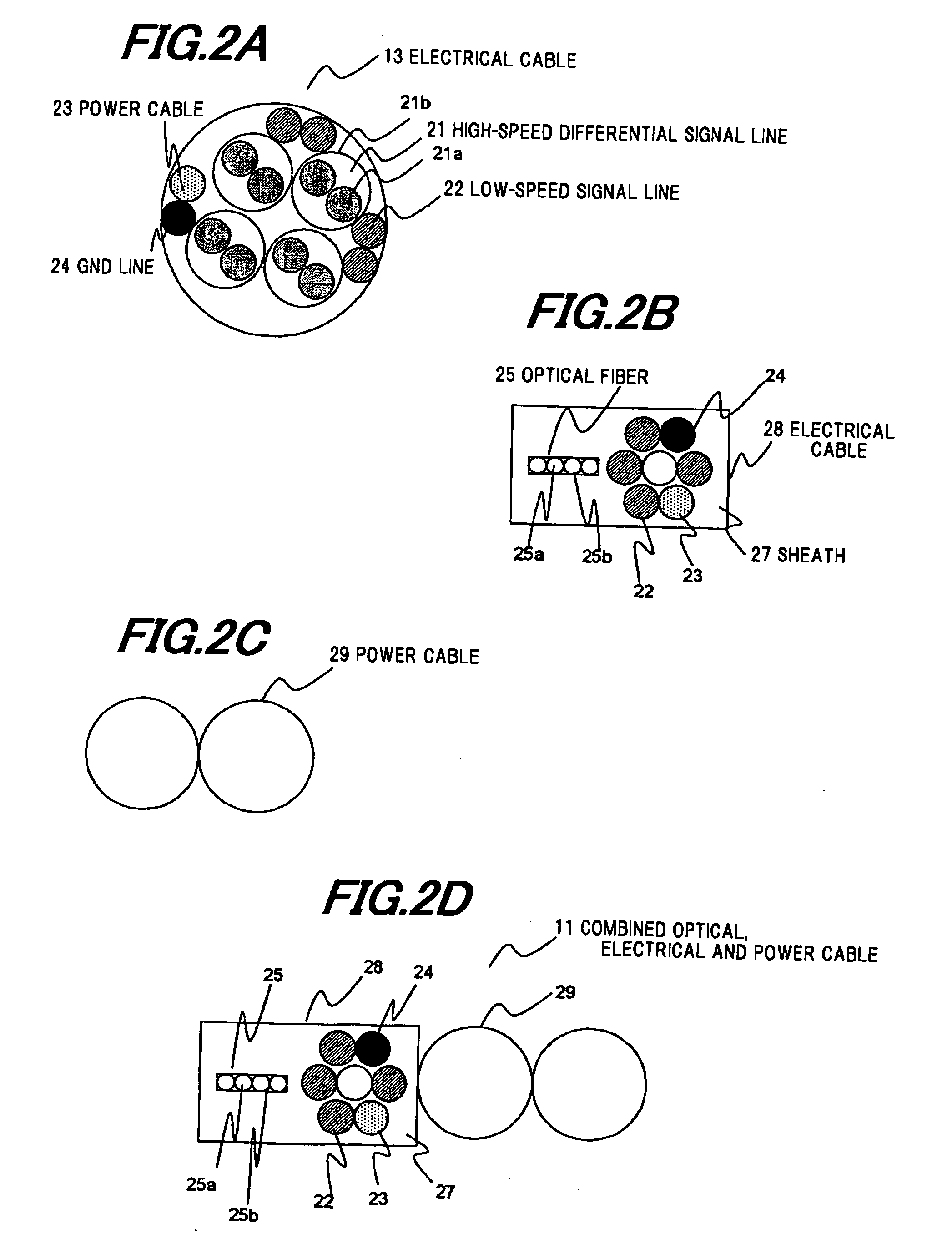
[0067]A combined optical and electrical transmission module 12 is connected to an electrical cable 13 with an electrical connector 14 connected to an external device (not shown). In FIG. 2A is shown one example of the cross-sectional structure of the electrical cable 13. It comprises high-speed differential signal lines 21 used as transmission lines whose signal transmission speed is not less than 10 Mbps and whose signal lines 21a are covered with a metallic tube or a metallic wire-braided shield 21b, low-speed signal lines 22 used as transmission lines whose signal transmission...


PUM


Abstract

A combined optical and electrical transmission assembly includes a combined optical, electrical and power cable having an optical fiber, electrical wiring and a power line combined therein or a combined optical and electrical cable having an optical fiber and electrical wiring combined therein, and a combined optical and electrical transmission module that includes an electrical-to-optical conversion unit having a laser for converting electrical signals to optical signals and a driving IC for driving the laser, and / or an optical-to-electrical conversion unit having a photodiode for converting optical signals to electrical signals and an amplification IC for amplifying electrical signals from the photodiode. The combined optical and electrical transmission module is connected to both ends of the combined optical, electrical and power cable or the combined optical and electrical cable. The combined optical and electrical transmission modules are each connected with an electrical cable for transmitting electrical signals with an external device and a power cable for transmitting power. The length of the power cable is shorter than that of the electrical cable.

Description

[0001]The present application is based on Japanese patent application No.2007-158159, the entire contents of which are incorporated herein by reference.BACKGROUND OF THE INVENTION[0002]1. Field of the Invention[0003]The present invention relates to a combined optical and electrical transmission assembly, which combines light and electricity to transmit signals and electrical power, and to a combined optical and electrical transmission module for electrical-to-optical or optical-to-electrical conversion.[0004]2. Description of the Related Art[0005]In recent years, with increasing display resolution and with increasing data dealt by information transmission device or storage device, there is an increasing demand for high-speed transmission lines capable of high-speed transmission of data. As high-speed transmission lines, there are used coaxial cables having a shield function, or differential transmission lines comprising a pair of differential lines in a shield, but their transmissio...

Claims


Application Information

Patent Timeline
IPC IPC(8): H04B10/00G02B6/42G02B6/44H01L31/0232H01S5/022H04B10/25
CPCG02B6/4214G02B6/4403G02B6/4416
Inventor YASUDA, HIROKIHIRANO, KOKIKOBAYASHI, MASAHIKO
Owner HITACHI CABLE
Learn More