Method of Attaching an Rfid Tag to a Component, a Component Comprising an Rfid Tag and Rfid Tag

Inactive Publication Date: 2008-12-18
BRYANT KEITH C
View PDF2 Cites 23 Cited by
  • Summary
  • Abstract
  • Description
  • Claims
  • Application Information

AI Technical Summary

Benefits of technology

[0025]Preferably, one or other of the housing of the RFID tag and the component comprises a protrusion extending therefrom, and the step of applying an ultrasonic welding process further comprises melting the protrusion to increase the strength of the weld after cooling.
[0029]Preferably, the step of applying an ultrasonic welding process further comprises melting a portion of the component which defines a wall of the recess and / or a portion of a peripheral edge of the housing abutting a wall of the recess to increase the strength of the weld after cooling.
[0036]One or more embodiments thereby provide a method of attaching an RFID tag to a component that results in a tamper evident, robust and secure product for use in Auto-ID applications, such as for containers for use within the pharmaceutical industry, which has considerable operational and cost benefits. Each component may be produced with an integral Radio Frequency Identity tag (RFID tag) that carries a unique identifier code. Each component may, thereby, be individually identified by remote reader capabilities, requiring no line-of-sight. The component may be identified throughout the process chain in which it is being used and information may be updated by writing directly to the tag and / or to a separate database. This may establish, inter alia, and in the case of the component being a container, that it has been filled with a specific product on a specific line at a specific time, moved on to a subsequent process or been even to a specific patient. A correct printed label may then be printed as and when required at any point of the packaging process and an update of both the database and the tag itself may be possible, if desired. The tagged component may allow confirmation and complete quality assurance at the completion of a process and, in the case of the component being a container, verification of the correct product being in the correct container, the correct container being at the correct process station, confirmation of the correct end user and the correct printed label being applied by correlation to the unique identification code and “stored” information.
[0040]Preferably, one or other of the housing of the RFID tag and the component comprises a protrusion extending therefrom, the protrusion being arranged to melt the protrusion on application of an ultrasonic welding process to increase the strength of the weld after cooling.
[0044]Thus, one or more embodiments of the present invention provide a component which has an RFID tag attached thereto which may be delivered to the customer already RFID enabled and does not require any special handling processes or additional operations. The RFID microchip and antenna are encased within a housing of the tag and are embedded in a double rigid package instead of on a flexible substrate thereby reducing the likelihood of suffering mechanical damage. Furthermore, one or more embodiments provide a component which has improved protection against damage due to harsh environmental conditions and / or sterilisation environments, as well as having anti-counterfeit and tamper proof attributes. Each component may have a unique serial number which may be difficult to change or replicate and therefore enables confirmation of origin.

Problems solved by technology

Modern manufacturing and supply chains are highly complex and competitive entities that rely on the ability to identify and track materials, work in progress and finished goods.
Barcode technology does, however, have many limitations including, for example, the following.
Barcodes may be rendered unreadable by dirt or damage.
Furthermore, barcodes may be easily reproduced and hence cannot provide any form of authentication.
Also, the most acceptable and widely used technology for printing barcodes is direct thermal printing and scanner readability is considered best with direct thermal printing, but this technology is extremely sensitive to environmental conditions such as heat and light (particularly fluorescent light and / or direct sunlight) and is not well suited to environments that results in exposure to such conditions, or even abrasion.
This is a time consuming process and adds to the expense of producing the labels.
Whilst RFID tagging has a number of advantages, difficulties may typically arise in affixing the RFID tags to the products to be tracked and / or identified.
The attachment of the RFID tag to the item of interest can be a complex and expensive process with implications for the user's manufacturing and handling processes.
However, these labels may be fragile and may suffer an unacceptable number of failures either during the initial application process or in subsequent handling.
Furthermore, smart labels are not generally suitable for irregularly shaped items, small bottles or containers of small radius.

Method used


Image

  • Method of Attaching an Rfid Tag to a Component, a Component Comprising an Rfid Tag and Rfid Tag
  • Method of Attaching an Rfid Tag to a Component, a Component Comprising an Rfid Tag and Rfid Tag
  • Method of Attaching an Rfid Tag to a Component, a Component Comprising an Rfid Tag and Rfid Tag

Examples


Embodiment Construction

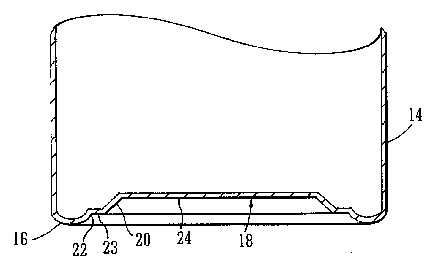
[0059]There is a real desire and need in industry for packaging to be manufactured with an integral RFID functionality, namely, an RFID enabled packaging component in which RFID tags are not applied like a label or attached by adhesive but are integrated into the packaging component itself to provide a practical and robust product.

[0060]Whilst there exist many different industries and many suitable products that would benefit from the application of RFID, the present invention will be described by way of examples in the context of containers for use in the packaging of pharmaceuticals. However, it will be appreciated that the methodology embodying the invention is not to be considered as being limited to the packaging of pharmaceuticals but may be applied to any container or product, preferably formed of a plastics material, that requires RFID enablement.

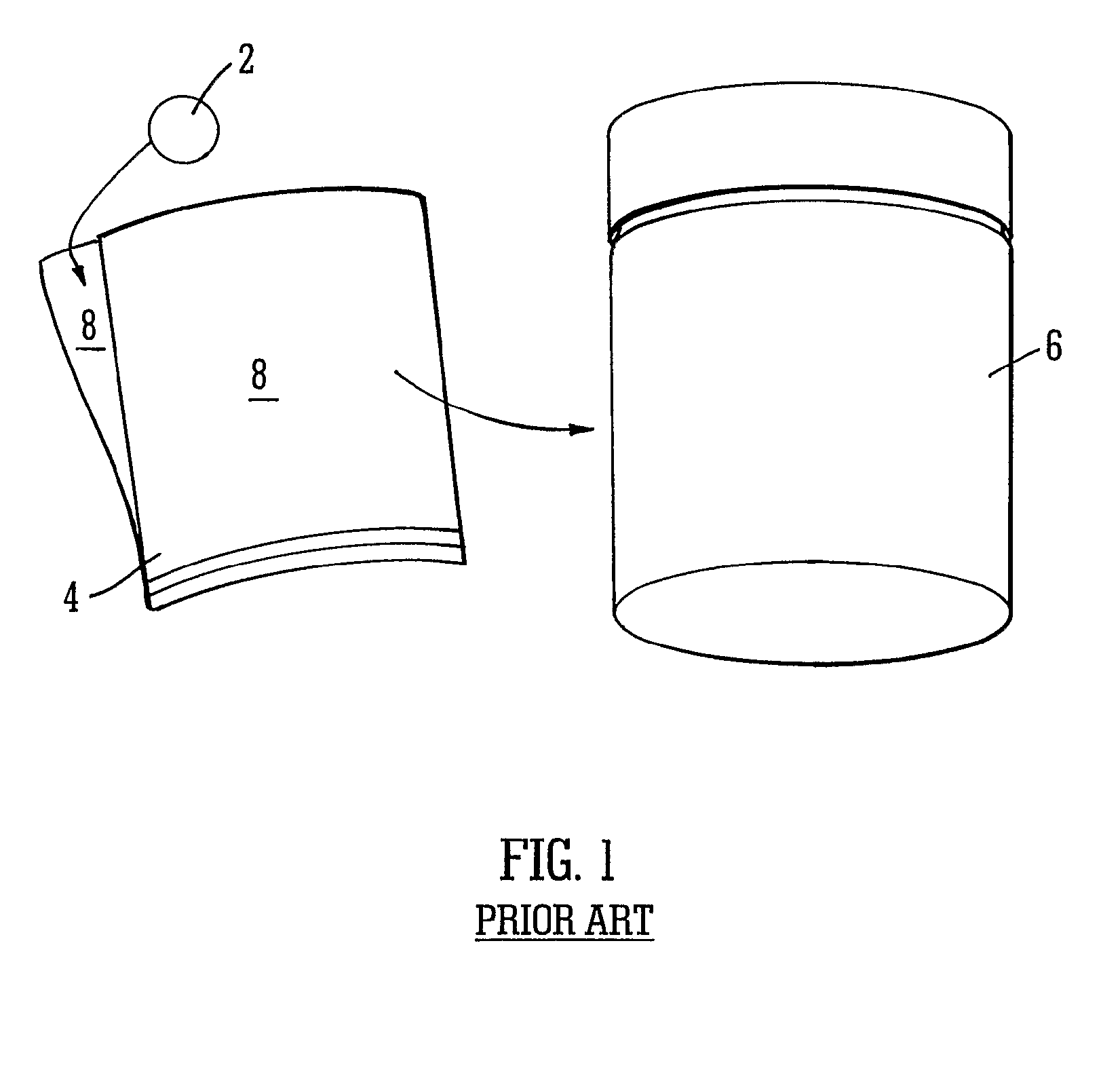
[0061]FIG. 1 shows a conventional RFID tag 2 to be incorporated in a conventional adhesive label 4 which may be attached to a typi...


PUM


Abstract

A method of attaching an RFID tag to a component comprises locating the RFID tag on or in a section of a component, applying an ultrasonic welding process to melt a portion of the housing and a portion of the component contacting the housing and allowing the component and the RFID tag to cool to form a weld therebetween. There is also described a comprising an RFID tag for identification wherein the RFID tag is ultrasonically welded to a section of the component. The RFID tag has a housing encapsulating control electronics and an antenna, the RFID tag being located on or in the section of the component, and wherein a portion of the housing and a portion of the component contacting the housing have a weld therebetween.

Description

FIELD OF THE INVENTION[0001]The present invention relates to a method of attaching an RFID tag to a component, a component comprising an RFID tag for identification and an RFID tag.BACKGROUND OF THE INVENTION[0002]Modern manufacturing and supply chains are highly complex and competitive entities that rely on the ability to identify and track materials, work in progress and finished goods. To reduce manpower costs and to reduce errors, systems for automatic identification have been developed and implemented over many years. The most widely used conventional auto identification technology uses barcodes containing identification information which may be printed on packaging materials or on labels that are attached to items of interest. This technology is very successful and may be economically applied to large volumes of low value items, hence its ubiquity in consumer goods and supermarkets.[0003]Barcode technology does, however, have many limitations including, for example, the follow...

Claims


Application Information

Patent Timeline
IPC IPC(8): G06K19/04G06K19/077
CPCG06K19/04G06K19/07749
Inventor BRYANT, KEITH C.
Owner BRYANT KEITH C
Why Eureka
Try Eureka