
Mesh free-space optical system for wireless local area network backhaul

a free space optical system and wireless local area network technology, applied in the field of wireless networks, can solve the problems of limited access to the network, limited patch cable length, and disadvantages of wired infrastructure, and achieve the effects of increasing network reliability, increasing network reliability, and increasing network capacity and provisioning

Inactive Publication Date: 2008-12-11
AT&T LABS
View PDF13 Cites 117 Cited by
  • Summary
  • Abstract
  • Description
  • Claims
  • Application Information

AI Technical Summary

Benefits of technology

[0010]Wireless local area network (WLAN) access points are typically connected to a core network via a WLAN backhaul network with fixed-line infrastructure such as twisted-pair cable, coax cable, or optical fiber. As the number of access points in a WLAN increases, and as they are deployed in a wide range of environments (including outdoors), the capacity and provisioning of the WLAN backhaul network becomes increasingly important. Embodiments of the invention connect the access points via free-space optical links, which do not require installation of physical media between access points. A WLAN backhaul network with a mesh topology provides increased network reliability through path redundancy. Supplementing the free-space optical links with millimeter wave (mm-wave) links provides increased network reliability through modal redundancy.

Problems solved by technology

There are disadvantages to a wired infrastructure.
From a user perspective, access to the network is limited to availability of a wall jack, and the length of the patch cable limits mobility.
In a Wi-Fi network with a small number of access points, throughput is commonly limited by the capacity of the RF links rather than the capacity of the backhaul network.
Providing backhaul network connections via fixed-line physical media such as twisted pair cable, coax cable, or optical fiber may be difficult and expensive.
In some instances, they may not be a viable option (for example, if requisite right-of-way cannot be obtained).

Method used


Image

  • Mesh free-space optical system for wireless local area network backhaul
  • Mesh free-space optical system for wireless local area network backhaul
  • Mesh free-space optical system for wireless local area network backhaul

Examples


Embodiment Construction

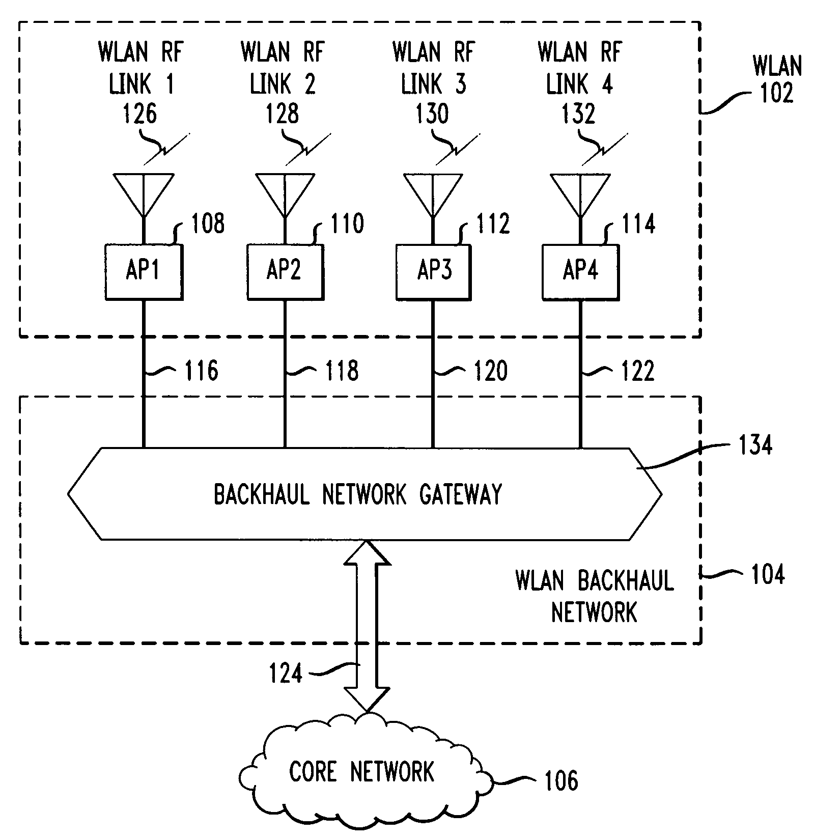
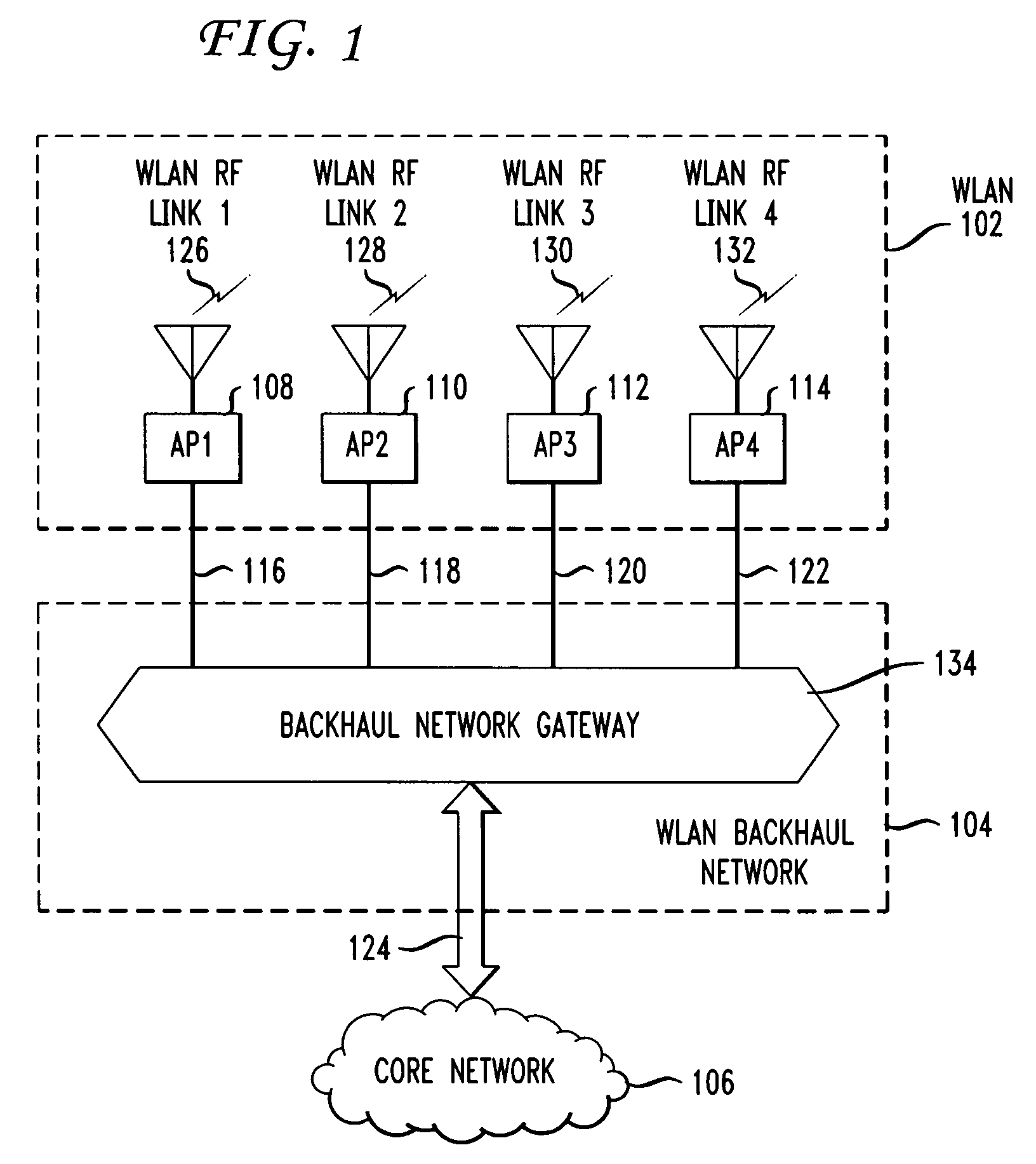
[0017]FIG. 1 shows a high-level schematic of a packet data network including WLAN 102, WLAN backhaul network 104, and core network 106. Herein, a Wi-Fi network complying with the IEEE 802.11 standard is used as an example of a WLAN. Embodiments of the invention, however, apply to other WLANs as well and are not restricted to Wi-Fi networks. WLAN 102 includes four access points AP1108-AP4114, with WLAN RF communication links WLAN RF link 1126-WLAN RF link 4132, respectively. Backhaul communication links 116-122 connect access points AP1108-AP4114 to backhaul network gateway 134, respectively. For simplicity, herein, a backhaul network gateway is referred to as a gateway. Communication link 124 connects gateway 134 to core network 106. In some instances, communication link 124 connects gateway 134 to an intermediate access network, such as an edge network, which then connects to a core network. Herein, WLAN backhaul network 104 includes the combined set of backhaul communication links...


PUM


Abstract

In wireless local area networks (WLANS) with a large number of access points, the provisioning and capacity of the WLAN backhaul network connecting the access points to a core network becomes a major issue in network design. Some network services call for access points to be deployed in high densities in a wide range of environments, including outdoor environments. Traditional backhaul networks using fixed media such as twisted pair cable, coax cable, or optical fiber, in many instances are not physically or economically viable. Disclosed are method and apparatus for connecting access points via a mesh network using free-space optical links. The free-space optical links may be supplemented with mm-wave links to increase reliability and capacity.

Description

[0001]This application claims the benefit of U.S. Provisional Application No. 60 / 933,765 filed Jun. 8, 2007, which is incorporated herein by reference.BACKGROUND OF THE INVENTION[0002]The present invention relates generally to wireless networks, and more particularly to mesh free-space optical systems for wireless backhaul networks.[0003]Popular communications services such as access to the global Internet, e-mail, and file downloads, are provided via connections to packet data networks. To date, user devices such as personal computers have commonly connected to a packet data network via a wired infrastructure. For example, a patch cable connects the Ethernet port on a personal computer to an Ethernet wall jack, which is connected by infrastructure cabling running through the walls of a building to network equipment such as a switch or router. There are disadvantages to a wired infrastructure. From a network perspective, providing packet data services to homes and commercial buildin...

Claims


Application Information

Patent Timeline
IPC IPC(8): H04B10/00
CPCH04B10/1125H04W84/12H04W88/10
Inventor MILLER, II, ROBERT RAYMONDBRITZ, DAVID MICHAEL
Owner AT&T LABS
Learn More