
Adjustable cooling apparatus

a cooling apparatus and adjustable technology, applied in lighting and heating apparatus, indirect heat exchangers, semiconductor/solid-state device details, etc., can solve the problems of affecting product reliability, affecting product reliability, and heat accumulation in the interior of the device, so as to speed up heat dispersion and improve cooling efficiency

Inactive Publication Date: 2008-12-11
TOPOWER COMP IND CO LTD
View PDF5 Cites 8 Cited by
  • Summary
  • Abstract
  • Description
  • Claims
  • Application Information

AI Technical Summary

Benefits of technology

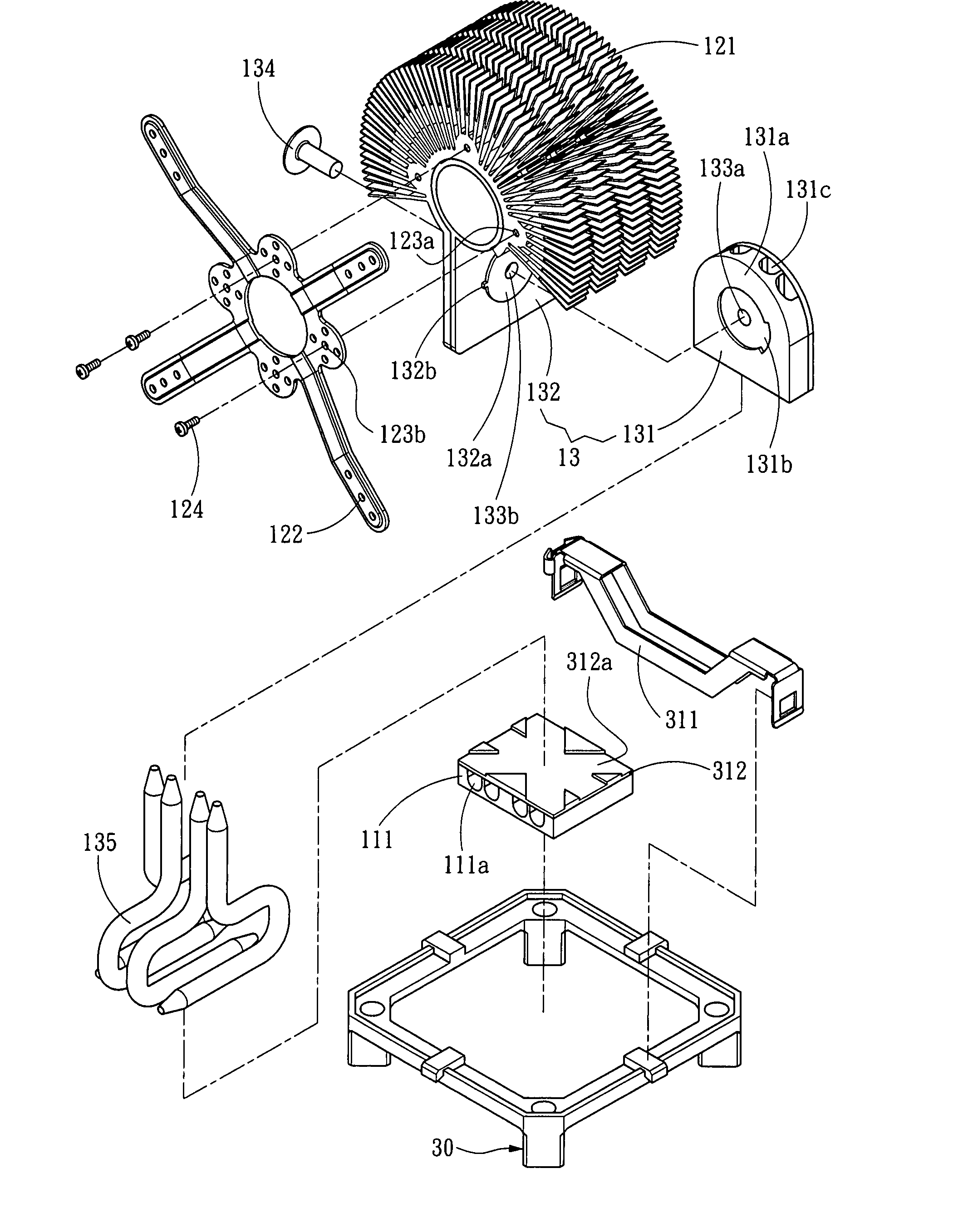
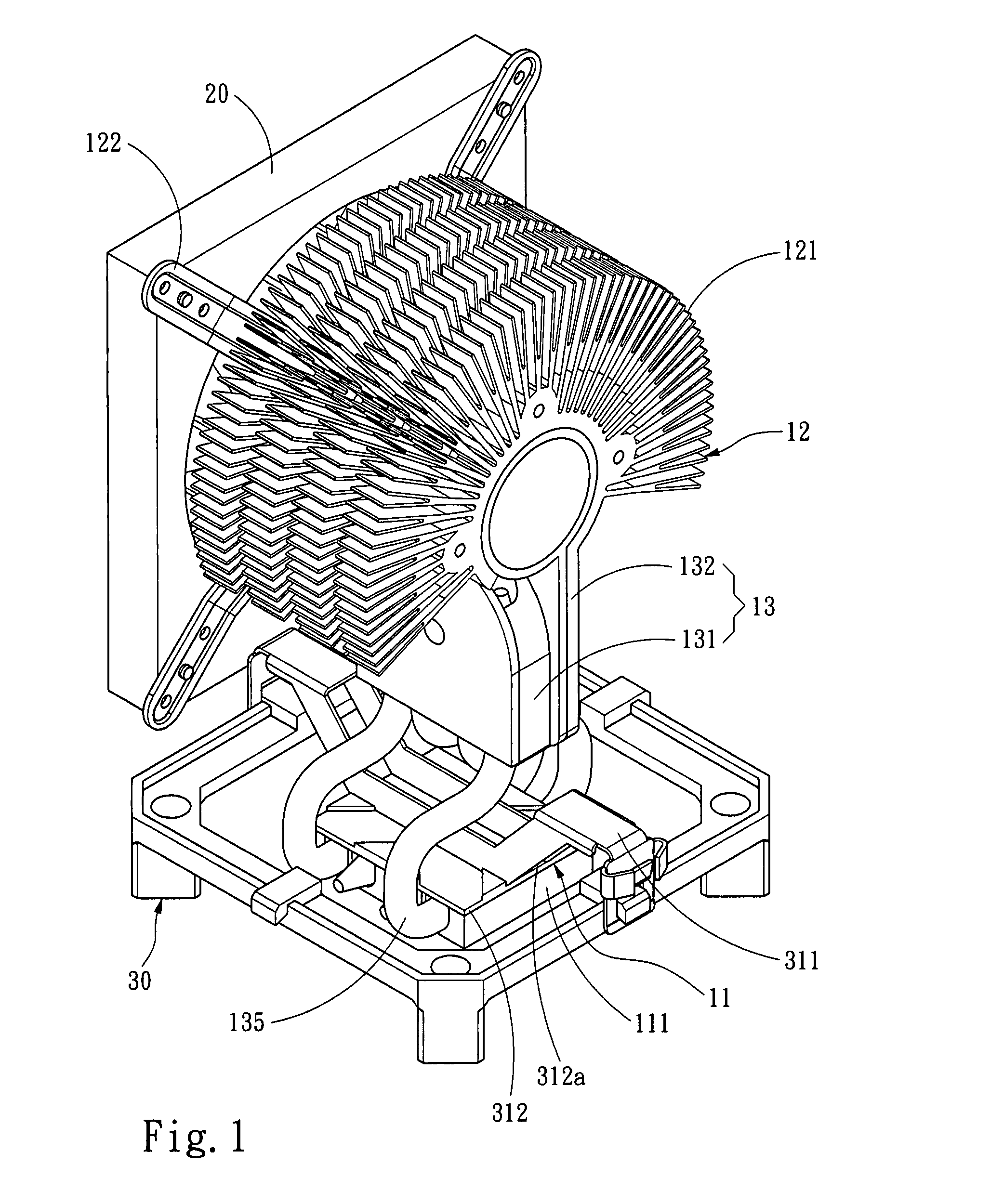
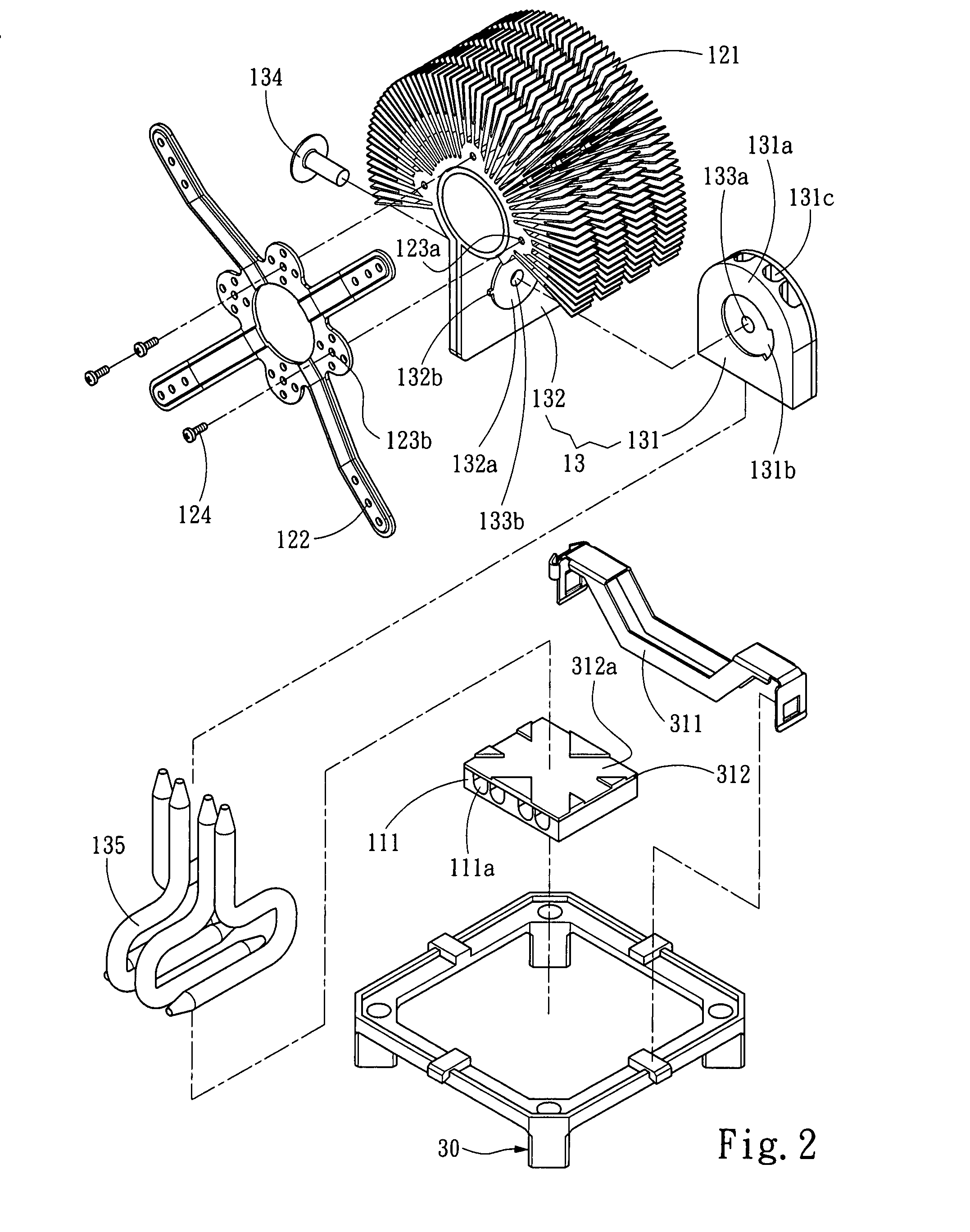
[0005]The primary object of the present invention is to provide a cooling apparatus with an adjustable heat dispersing direction to resolve the problems of airflow turbulence and heat accumulation in electronic products that occur to the conventional techniques by dispersing heat in only one direction. To achieve the foregoing object the present invention provides an adjustable cooling apparatus to be used on electronic devices to disperse heat. It mainly includes a heat transfer portion to transfer heat of an electronic device and a heat dispersing portion to receive and disperse the heat from the heat transfer portion. The heat transfer portion and the heat dispersing portion are coupled through a toggle mechanism. The toggle mechanism includes a first coupling unit connecting to the heat transfer portion and a second coupling unit connecting to the heat dispersing portion. The first and second coupling units are pivotally coupled through a shaft so that they can be swiveled relative to each other. The heat dispersing portion and the heat transfer portion may form an angle relative to each other that is adjustable through the toggle mechanism which serves as an axis. Moreover, the heat transfer portion has a base mounted onto the electronic device. The base has a turning mechanism fastened to the heat transfer portion. The turning mechanism includes a first turning unit fastened to the base and a second turning unit fastened to the heat transfer portion. Thus the swivel direction of the cooling apparatus relative to the electronic device can be adjusted. To improve cooling efficiency an air fan is installed on the heat dispersing portion to drive airflow to pass through the heat dispersing portion to speed up heat dispersion.
[0006]The adjustable cooling apparatus of the invention has the toggle mechanism and turning mechanism to adjust the heat dispersing direction. Besides adjusting the heat dispersing direction in response to the internal space of the electronic device to achieve faster cooling effect for the electronic device, the heat dispersing direction may also be adjusted and directed towards the interior or electronic elements of other electronic products to drive airflow to pass through to aid cooling effect. Hence an optimal cooling efficiency can be achieved for the entire set of electronic product.

Problems solved by technology

To build high performance in a smaller size, reliability becomes an important issue.
An electronic device generates heat during high speed process that affects product reliability.
As the size of the electronic device becomes smaller, heat accumulation in the interior of the device is a big problem which the industry constantly tries to figure out a better solution.
However, the conventional active and passive cooling elements mostly are installed in a fixed manner, and disperse heat only in a single direction.
As the internal elements of electronic products often are arranged in a complex manner and form obstacles in an irregular space, cooling airflow in one direction cannot be smoothly discharged, and turbulence often happens.
Hence heat trapping and accumulation in the small internal space becomes a serious problem.

Method used


Image

  • Adjustable cooling apparatus
  • Adjustable cooling apparatus
  • Adjustable cooling apparatus

Examples


Embodiment Construction

[0014]Please refer to FIGS. 1 and 2 for an embodiment of the invention. The adjustable cooling apparatus of the invention is aims to disperse heat generated by an electronic device (not shown in the drawings). It mainly includes a heat transfer portion 11 to transfer heat of the electronic device and a heat dispersing portion 12 to receive the heat from the heat transfer portion 11 and disperse the heat. The heat transfer portion 11 has a heat transfer member 111 attached to a heat source of the electronic device. The heat dispersing portion 12 has a radiation fin assembly 121. The cooling apparatus further has a toggle mechanism 13 to couple the heat transfer portion 11 and the heat dispersing portion 12. The heat dispersing portion 12 and the heat transfer portion 11 form an angle between them that can be adjusted about an axis served by the toggle mechanism 13. The toggle mechanism 13 includes a heat transfer duct 135 coupled with the heat transfer portion 11. The heat dispersing...


PUM


Abstract

An adjustable cooling apparatus to disperse heat generated by an electronic device mainly includes a heat transfer portion attached to the electronic device to transfer heat generated by the electronic device and a heat dispersing portion to receive the heat from the heat transfer portion and disperse the heat. The heat transfer portion and the heat dispersing portion are coupled through a toggle mechanism such that the heat dispersing portion can be tilted relative to the heat transfer portion at an angle which is adjustable. The cooling apparatus is mounted onto the electronic device through a base. The base has a turning mechanism coupling with the heat transfer portion so that the cooling apparatus is swivelable in a desired direction relative to the electronic device. An air fan is fastened to the heat dispersing portion to drive airflow to pass through the heat dispersing portion to improve cooling efficiency.

Description

FIELD OF THE INVENTION[0001]The present invention relates to a cooling apparatus and particularly to a cooling apparatus with an adjustable heat dispersing direction to be used on electronic devices.BACKGROUND OF THE INVENTION[0002]These days the performance and speed of electronic products improve very rapidly. With advance of material technology the electronic products have been made smaller and lighter. To build high performance in a smaller size, reliability becomes an important issue. An electronic device generates heat during high speed process that affects product reliability. As the size of the electronic device becomes smaller, heat accumulation in the interior of the device is a big problem which the industry constantly tries to figure out a better solution.[0003]The commonly adopted cooling techniques for electronic devices at present can be divided into active cooling and passive cooling. Active cooling, such as cooling fans and water circulation, uses an extra driving s...

Claims


Application Information

Patent Timeline
Patent Type & Authority Applications(United States)
IPC IPC(8): H05K7/20
CPCF28F1/12F28F13/00H01L23/36H01L23/40H01L23/427H01L23/467H01L2924/0002F28F2280/105F28F2013/005H01L2924/00
Inventor CHEN, MICHAEL
Owner TOPOWER COMP IND CO LTD
Learn More