
Stair assist robot mechanism and method

a technology of robots and stair climbers, applied in the field of robots and remote controlled mobile robots, can solve the problems of affecting the operation of other robots, and adding to the cost and complexity of the robot,

Inactive Publication Date: 2008-12-04
FOSTER-MILLER
View PDF29 Cites 30 Cited by
  • Summary
  • Abstract
  • Description
  • Claims
  • Application Information

AI Technical Summary

Benefits of technology

[0010]Typically, the ski structure is releasably connected to the first arm. There may be snap fit receptacles which receive therein structure of the first arm. Preferably, the ski structure includes a forward angled toe and a rearward angled heel. The preferred ski structure may also include an anti-slide feature thereon for preventing sliding of the ski structure with respect to the robot arm. In one example, the ski structure includes a snap fit receptacle which receives therein the first arm and the anti-slide feature includes a cut out in a side of the snap fit receptacle. The preferred ski structure may also include an anti-rotation feature thereon for preventing rotation of the ski structure with respect to the robot arm. In one example, the ski structure includes a snap fit receptacle which receives therein the first arm and the anti-rotation feature includes an orifice in the snap fit receptacle. The ski structure may also include a forward guard portion. Ties may be included for securing the ski structure to the first arm.
[0012]The subject invention also features a stair assist mechanism for a mobile robot. The preferred mechanism comprises a ski structure including a receptacles (e.g., snap fit receptacles) which receive therein an arm of the mobile robot. A forward upwardly angled toe is on the ski structure, and a rearward upwardly angled heel is also on the ski structure. The ski structure may include an anti-slide feature thereon for preventing sliding of the ski structure with respect to the robot arm. One anti-slide feature includes a cut out in a side of a receptacle. The ski structure may also include an anti-rotation feature thereon for preventing rotation of the ski structure with respect to the robot arm. One anti-rotation feature includes an orifice in a receptacle. The ski structure may also include a forward guard portion. Ties may be provided for securing the ski structure to the robot arm.

Problems solved by technology

Often, the stair climbing components of the robot interfere with other operations carried out by the robot.
These stair climbing tracks, however, add to the cost and complexity of the robot and may interfere with or limit other robot operations in the field.

Method used


Image

  • Stair assist robot mechanism and method
  • Stair assist robot mechanism and method
  • Stair assist robot mechanism and method

Examples


Embodiment Construction

[0027]Aside from the preferred embodiment or embodiments disclosed below, this invention is capable of other embodiments and of being practiced or being carried out in various ways. Thus, it is to be understood that the invention is not limited in its application to the details of construction and the arrangements of components set forth in the following description or illustrated in the drawings. If only one embodiment is described herein, the claims hereof are not to be limited to that embodiment. Moreover, the claims hereof are not to be read restrictively unless there is clear and convincing evidence manifesting a certain exclusion, restriction, or disclaimer.

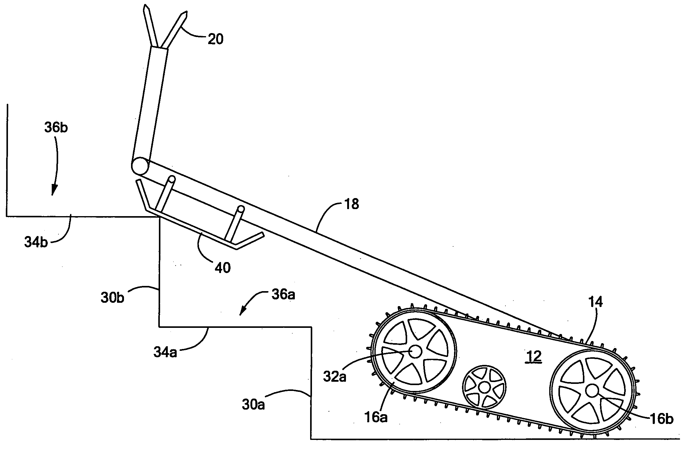
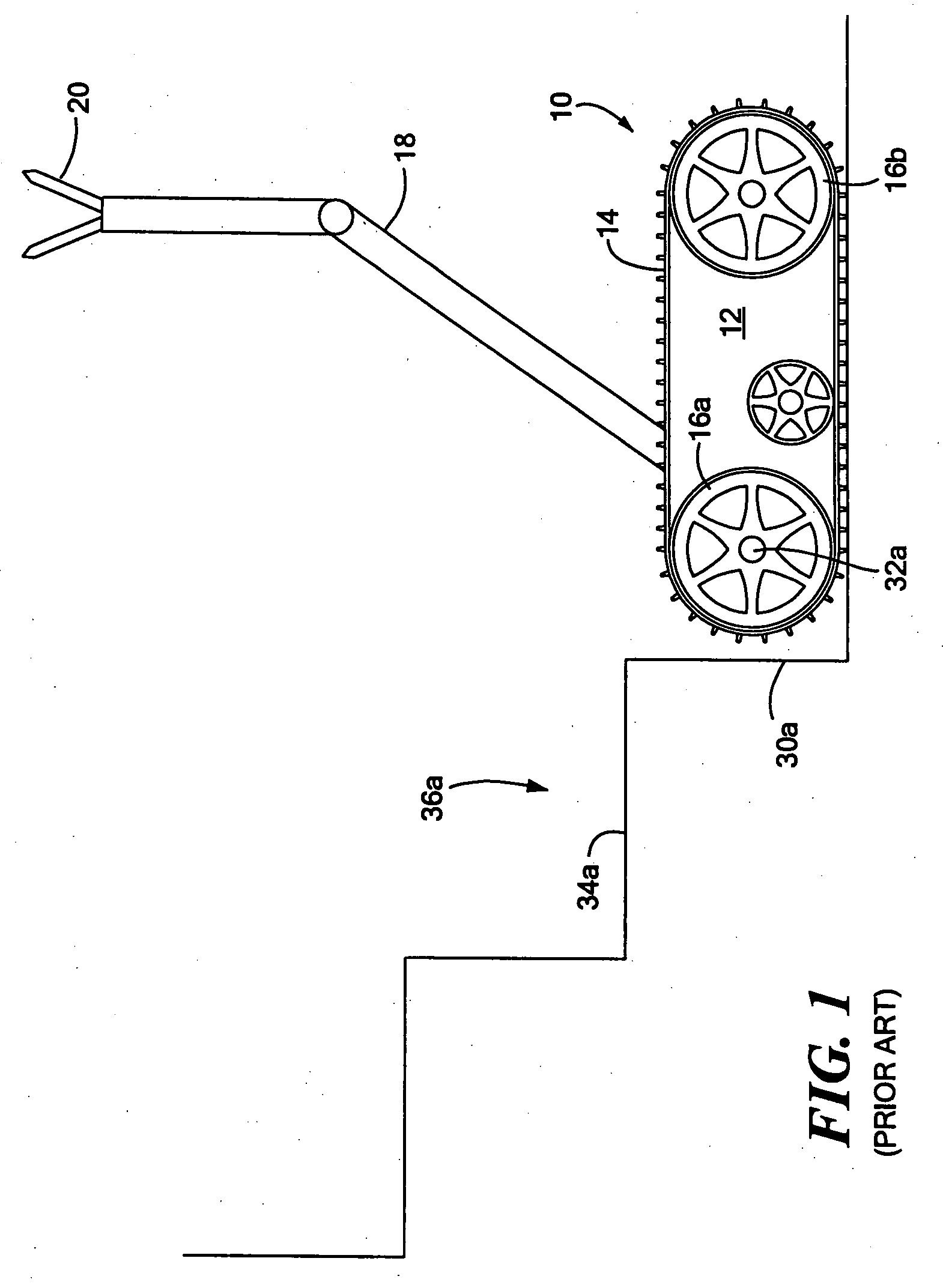
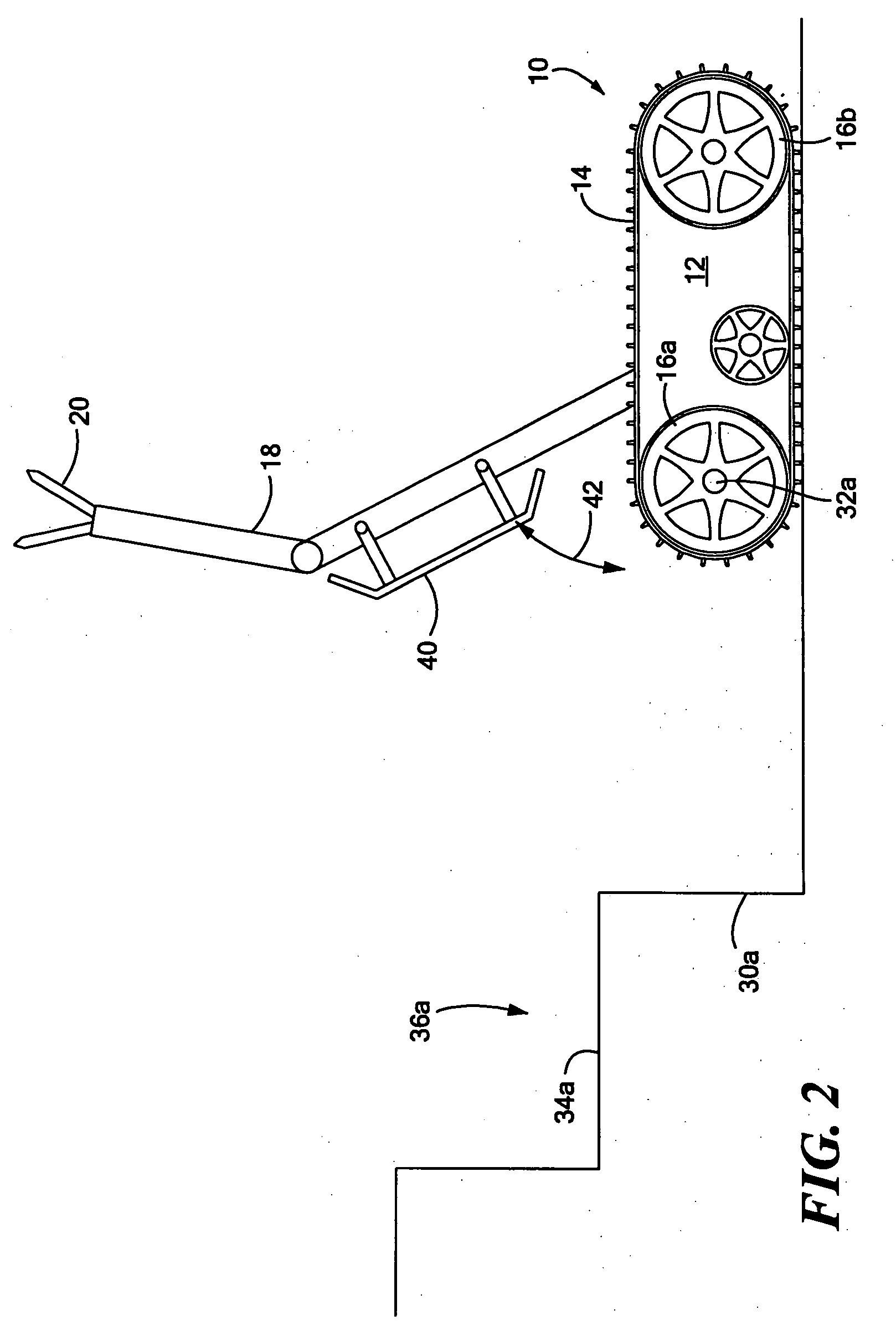
[0028]FIG. 1 shows robot 10 with chassis 12 and side drive mechanisms in a form of track 14 driven by wheels 16a and 16b. Robot 10 includes working robot arm 18 with end effector 20. Such a robot configuration is fairly common and includes the applicant's TALON® robot (Foster-Miller, Inc., Waltham, Mass.). When robot 10 app...


PUM


Abstract

A mobile robot with a chassis including one or more drive mechanisms and at least a first arm pivotably connected to the chassis and configured to pitch up and down. A ski structure is attached on an underside of the first arm for raising the chassis as the arm is pitched down so the drive mechanisms can traverse a riser in the path of the chassis.

Description

FIELD OF THE INVENTION[0001]This subject invention relates to robots, remote controlled mobile robots in particular, and a mechanism which assists a mobile robot in climbing stairs.BACKGROUND OF THE INVENTION[0002]Robotic engineers have long designed different robot configurations for climbing stairs with varying degrees of success. Often, the stair climbing components of the robot interfere with other operations carried out by the robot. See U.S. Pat. Nos. 4,993,912 and 7,011,171. Some stair climbing robots have side tracks and also specialized rotateable stair climbing tracks which assist the robot in climbing stairs. These stair climbing tracks, however, add to the cost and complexity of the robot and may interfere with or limit other robot operations in the field.SUMMARY OF THE INVENTION[0003]It is therefore an object of this invention to provide a new mobile robot able to climb stairs.[0004]It is a further object of this invention to provide such a mobile robot which does not r...

Claims


Application Information

Patent Timeline
IPC IPC(8): B25J11/00
CPCB25J5/005B62D55/075B62D57/024
Inventor LANGFORD, CHRISTOPHER J.SARKIS, JENNIFER R.DEAN, CHARLES EDWINWALDEN, JOHN
Owner FOSTER-MILLER
Learn More