Eureka AIR delivers breakthrough ideas for toughest innovation challenges, trusted by R&D personnel around the world.

Valve device having barrier for suppressing transmission of pulsating waves

a valve device and pulsating wave technology, applied in the direction of valves, mechanical devices, valve operating means/releasing devices, etc., can solve the problems of increasing the size of the purge valve, and achieve the effect of reducing nois

Active Publication Date: 2008-11-27
DENSO CORP
View PDF4 Cites 17 Cited by
  • Summary
  • Abstract
  • Description
  • Claims
  • Application Information

AI Technical Summary

Benefits of technology

[0008]The present invention has been made in view of the above-mentioned problem, and an object of the present invention is to provide an improved valve device, in which transmission of pulsating waves is suppressed without increasing a size of the valve device.
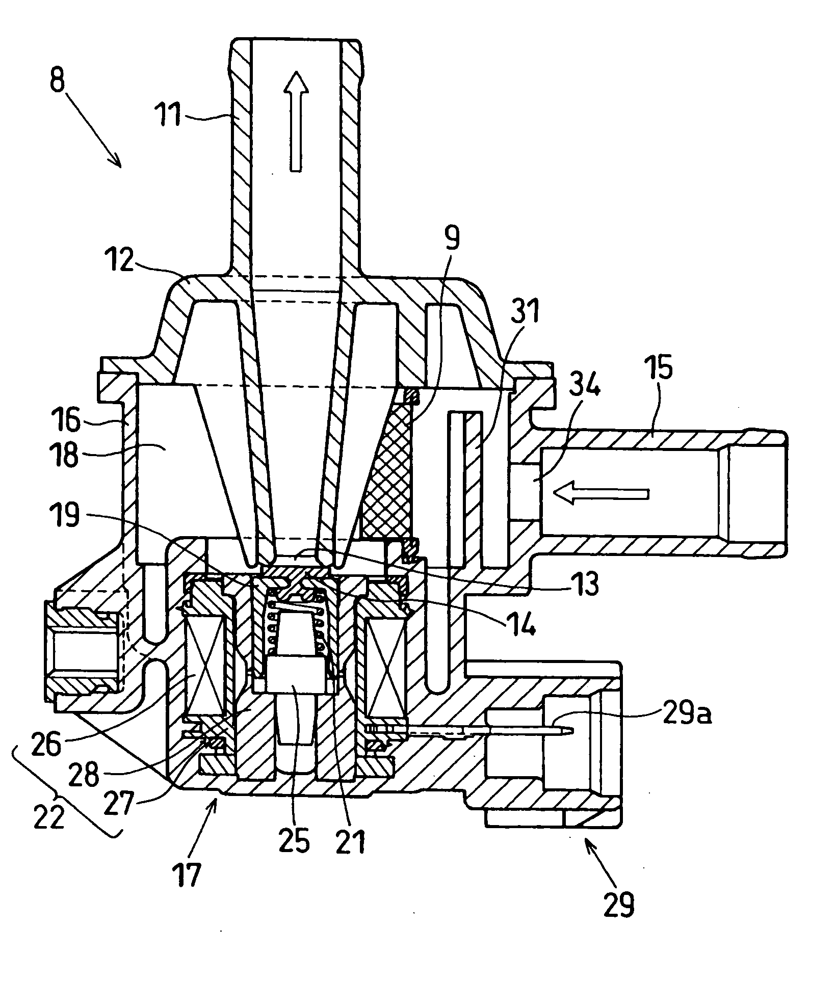
[0010]The valve port is normally closed by a valve body that is biased by a biasing spring to a direction to close the valve port. The valve body is driven by an electromagnetic actuator to thereby open the valve port. When the valve port is opened, the evaporated fuel stored in the canister is purged into the engine through the purge valve. The purge valve also includes an enlarged chamber for reducing an amount of pulsating waves generated in the purge valve.
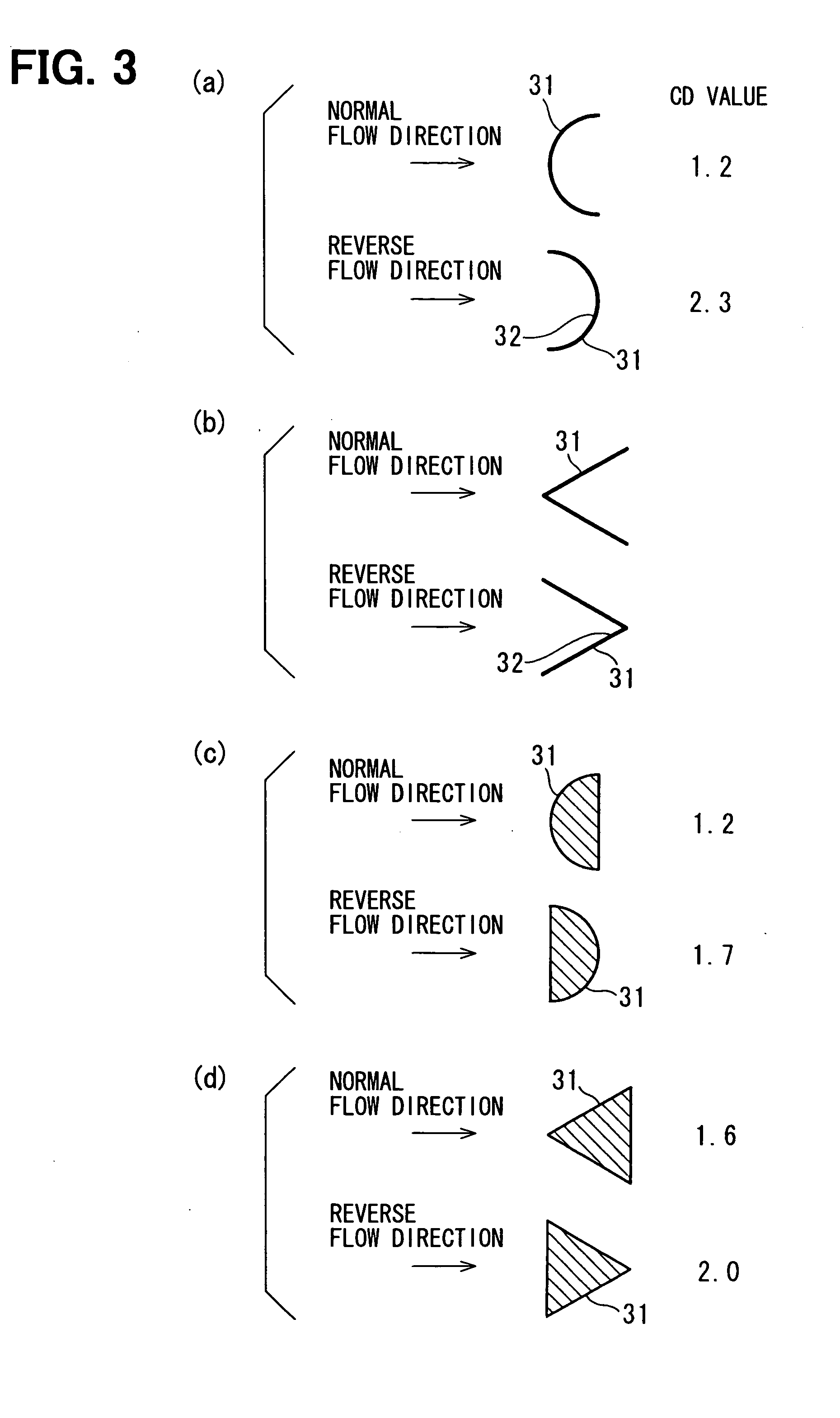
[0011]A barrier pillar is disposed in the fluid passage between the inlet port and the valve port to suppress transmission of the pulsating waves to the canister through the input port. The barrier pillar has a low flow resistance in a normal flow direction from the inlet port to the valve port, and a higher flow resistance in a reverse flow direction from the valve port to the inlet port. Accordingly, transmission of the pulsating waves generated in the purge valve to the canister is suppressed by the barrier pillar, while the evaporated fuel smoothly flows into the purge valve from the canister without being much disturbed by the barrier pillar.
[0013]According to the present invention, transmission of the pulsating waves generated in the purge valve to the canister is well suppressed without increasing a volume of the purge valve, thereby reducing noises due to the pulsating waves. Other objects and features of the present invention will become more readily apparent from a better understanding of the preferred embodiment described below with reference to the following drawings.

Problems solved by technology

However, there is a problem that a size of the purge valve becomes large by enlarging the space for suppressing the pulsating waves.
To suppress generation of the large amount of the pulsating waves, the suppressing space having a large volume is required, resulting in increase in the size of the purge valve.
The same problem is similarly involved in valve devices other than the purge valve.

Method used


Image

  • Valve device having barrier for suppressing transmission of pulsating waves
  • Valve device having barrier for suppressing transmission of pulsating waves
  • Valve device having barrier for suppressing transmission of pulsating waves

Examples


Embodiment Construction

[0024]A preferred embodiment of the present invention will be described with reference to accompanying drawings. A valve device of the present invention is advantageously used as a purge valve disposed between an internal combustion engine and a canister for storing evaporated fuel therein. First, referring to FIG. 10, an entire purge system for an internal combustion engine will be explained.

[0025]Fuel evaporated in a fuel tank 1 is absorbed and stored in a canister 2. Atmospheric air is introduced into the canister 2 through a filter 10, an air-introducing passage 3 and a release valve 7. The canister 2 is connected to an intake pipe 5 of the internal combustion engine at a downstream portion of a throttle valve 6 through a purging passage 4. A purge valve 8 having a filter 9 there in is disposed in the purging passage 4. By opening the release valve 7 and the purge valve 8 while the engine is being operated, the evaporated fuel stored in the canister 2 is introduced into the inta...


PUM


Abstract

A present invention is advantageously applied to a purge valve for purging evaporated fuel stored in a canister to an intake pipe of an engine. The purge valve has a fluid passage connecting an inlet port and an outlet port, and a normally closed valve port that is selectively opened by operation of an electromagnetic actuator is disposed in the fluid passage. A barrier pillar is disposed in the fluid passage between the inlet port and the valve port to suppress transmission of pulsating waves generated in the purge valve to the canister. Flow resistance of the barrier pillar is higher in a reverse flow direction from the valve port to the inlet port than in a normal flow direction from the inlet port to the valve port. The transmission of the pulsating waves is well suppressed by the barrier pillar while allowing a smooth flow from the canister into the purge valve.

Description

CROSS-REFERENCE TO RELATED APPLICATION[0001]This application is based upon and claims benefit of priority of Japanese Patent Application No. 2007-138104 filed on May 24, 2007, the content of which is incorporated herein by reference.BACKGROUND OF THE INVENTION[0002]1. Field of the Invention[0003]The present invention relates to a valve device for opening or closing a fluid passage and especially to such a valve device used as a purge valve for purging evaporated fuel stored in a canister mounted on an automotive vehicle.[0004]2. Description of Related Art[0005]In a valve device, pulsating waves are generated when a valve port in a fluid passage is abruptly closed, and the pulsating waves are transmitted to an upstream portion of the valve port. This phenomenon is known as a water-hammer phenomenon. For example, in a purge valve disposed in a passage between an engine and a canister for selectively supplying evaporated fuel stored in the canister to the engine, pulsating pressure wav...

Claims


Application Information

Patent Timeline
Patent Type & Authority Applications(United States)
IPC IPC(8): F16L55/04
CPCF16L55/055F16L55/07
Inventor OKUDA, HIDEKI
Owner DENSO CORP
Why Eureka
Eureka Blog
Learn More