
Retrieval and fall arrest system for manhole applications

a technology for manholes and applications, applied in underwater structures, foundation engineering, construction, etc., can solve the problems of inadequate fresh air supply, noxious or toxic fumes to persons in underground vaults, and various forms of manhole hoists and fall arrest systems that have been employed in the past have only limited success, and achieve high load bearing lift capacity

Inactive Publication Date: 2008-11-27
T A PELSUE
View PDF19 Cites 14 Cited by
  • Summary
  • Abstract
  • Description
  • Claims
  • Application Information

AI Technical Summary

Benefits of technology

[0012]The present invention provides an integrated, portable manhole guard and manhole hoist that does not obstruct passage of personnel and materials through the manhole and provides fall arrest and high load bearing lift capacity. The device comprises a separately foldable base constituting the essential structure of the manhole guard and a separately foldable top portion comprising the hoist and fall arrest support structure.
[0013]The base can be folded into a folded position for shipment and storage separately from the top. In the expanded position, the base comprises three sides of a rectangle forming the guard structure to keep people from inadvertently encountering the manhole and an open side permitting the entry and exit of personnel and materials. This open side can be closed by various temporary means so that inadvertent access to the manhole is prevented on all sides. The base also includes “locking” means to align the base for installation of the top portion, to provide stability for the erected base and to prevent the base from inadvertently folding from the erected position during use.

Problems solved by technology

Personnel in the underground vault may be subjected to noxious or toxic fumes and may otherwise have an inadequate supply of fresh air.
The various forms of manhole hoists and fall arrest systems that have been employed in the past have met with only limited success.
Among other things, prior art hoists have not included a manhole guard or have not cooperated well with the guard thereby interfering with access of personnel and materials through the manhole.
Prior art hoists have failed to provide adequate load capacity or fall arrest protection.
These hoists do not include a manhole guard, and they do not interact well with typical manhole guards thereby interfering with a worker's easy entry and exit via the manhole.
When used with a manhole guard, the narrow footprint of the legs is constrained thereby limiting the stability and lifting capacity of these hoists.
Unfortunately, the cross-bar in the “H” extends over a portion of the manhole opening thereby interfering with and limiting the passage of personnel, materials and tools into and from the underground vault.
In addition, the use of a single upwardly extending arm also significantly limits the lifting capacity of the hoist.
Attempts have been made to improve these hoist systems, but the “improvements” have also met with only limited success.
While these systems do not completely obscure the manhole opening, they still restrict access by personnel, because the handrail of the manhole guard is usually between waist and chest level on a typical worker.
Thus, the crossbar and pulley still interfere with a worker who must crouch down or even sit to access or leave the manhole.
Also, the lifting capacity of these devices is limited by the fact that the load is supported from the single horizontal crossbar which itself rests on two of the handrails of the manhole guard.
Such a device is much more expensive than the other prior art systems.
It is difficult to align over a manhole, and its application is limited to manholes that are not impeded vis-à-vis other structures, e.g., walls, curbs, and / or parked vehicles.

Method used


Image

  • Retrieval and fall arrest system for manhole applications
  • Retrieval and fall arrest system for manhole applications
  • Retrieval and fall arrest system for manhole applications

Examples


Embodiment Construction

[0043]The invention is now described with reference to preferred embodiments as depicted in the drawings and described herein.

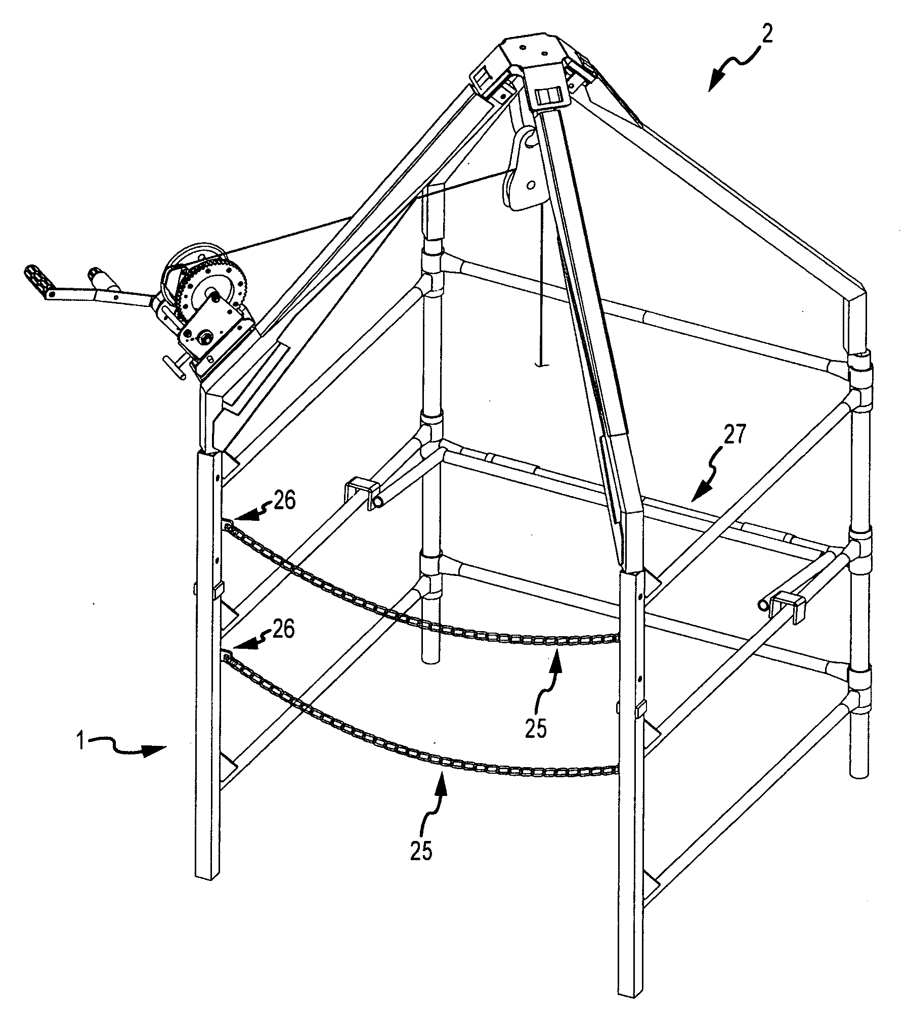
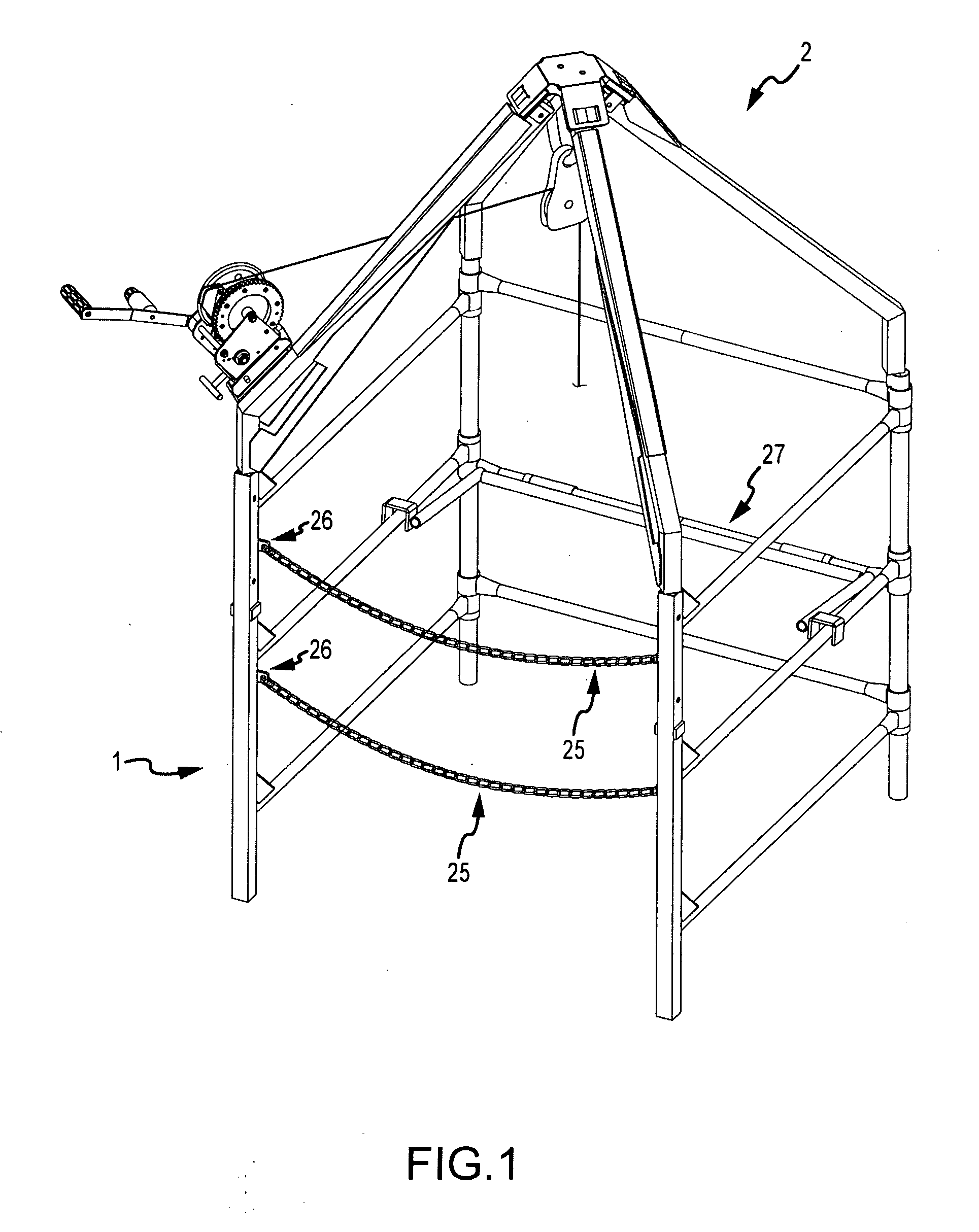
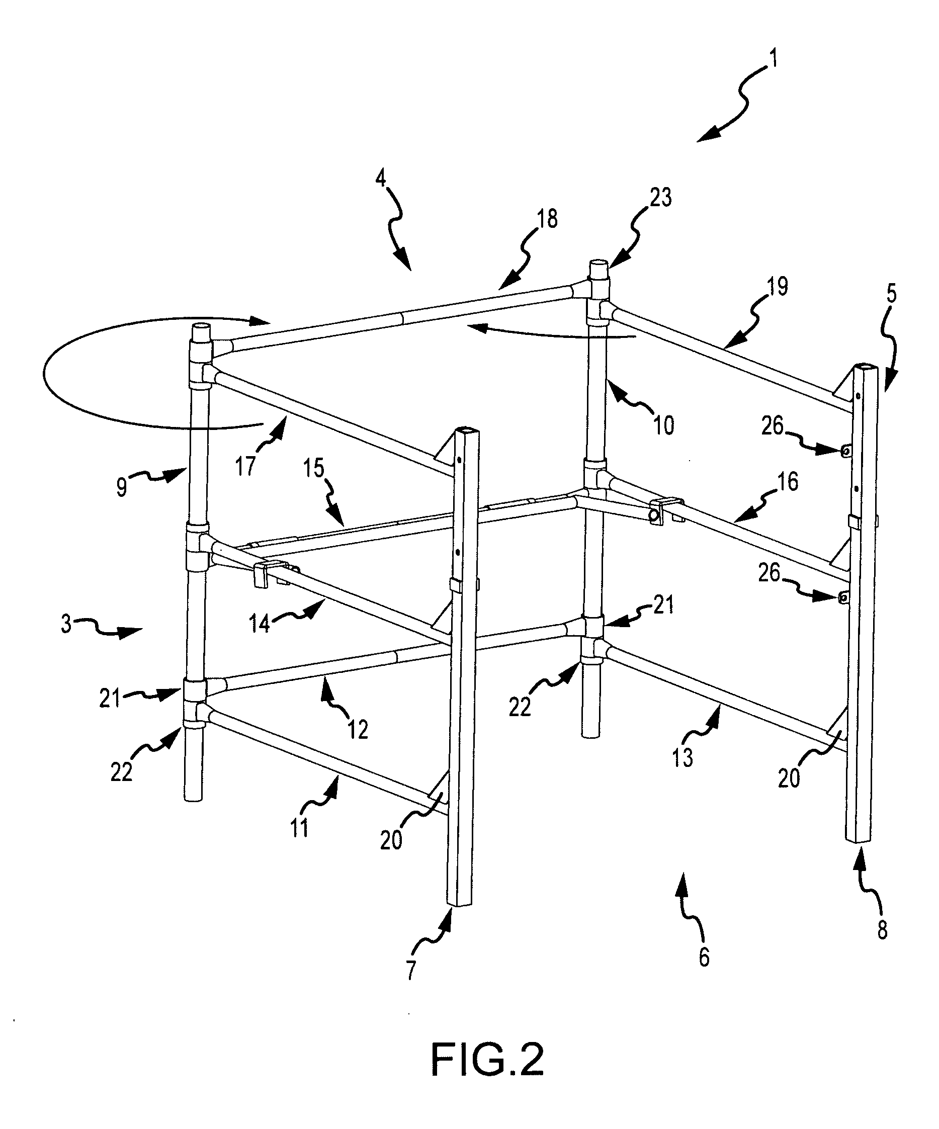
[0044]FIG. 1 depicts one embodiment of the present invention in an erected and assembled condition ready for use. As illustrated in FIGS. 1, 2 and 7, the present invention includes a lower portion or base 1 and an upper portion 2 which is mounted on the base. The lower portion shown in FIG. 2 contains the essential features of a typical manhole guard. The upper portion shown in FIG. 7 contains the features of the hoist and also serves as part of the guard. FIG. 1 shows the upper portion or hoist 2 mounted on the lower portion 1.

[0045]The term “hoist” as used herein should not be construed to mean a device for raising and lowering things, i.e., tools, parts or equipment, exclusively. Indeed, the principal use of the “hoist” is to raise and lower individual workers into and out of the vault. In many instances, the hoist may also be used to position the worker a...


PUM


Abstract

A foldable hoist, fall-arrest and recovery system to be used in connection with a rectangular manhole guard having vertical posts at four corners of the guard including an upper structure having four elongated support members forming a pyramid shaped structure with the base of each of the support members being securely mounted to the top of a post on the manhole guard and the other ends of the support members being pivotally connected to an apex so that the upper structure can be folded for storage and shipment when disconnected from the base and means connected at the apex for raising and lowering workers and / or cargo into and out of the manhole or for arresting the fall or recovering a worker.

Description

[0001]This application claims the benefit of U.S. provisional patent application Ser. No. 60 / 927,210, filed on May 2, 2007, which is incorporated by reference herein.I. FIELD OF THE INVENTION[0002]The invention relates to the field of manhole safety protection systems, in particular to manhole guards and to devices for transporting materials and personnel through the manhole into an underground vault. In particular, the invention relates to devices for safely arresting the fall of a worker entering an underground vault or confined space and for recovering a worker from an underground vault or confined space.II. BACKGROUND OF THE INVENTION[0003]For a number of reasons, the utility “infrastructure” for urban society is implemented in significant part using underground facilities. Among other things, electric, gas, telecommunication and water services are distributed in part underground. Sewer systems remove surface waste water via underground conduits. To service this infrastructure, ...

Claims


Application Information

Patent Timeline
Patent Type & Authority Applications(United States)
IPC IPC(8): A62B1/08
CPCA62B1/04E02D29/127E02D29/122
Inventor PELSUE, BRADLEY A.INMAN, EDWARD J.PETERS, TIMOTHY G.DUKE, CHRISTOPHER J.NIKSIC, MARK R.
Owner T A PELSUE
Learn More